Table of Contents
Advertisement
Quick Links
Advertisement
Table of Contents
Troubleshooting

Related Manuals for IEI Technology DRPC-230-ULT5 Series


Summary of Contents for IEI Technology DRPC-230-ULT5 Series
- Page 1 DRPC-230-ULT5 Embedded System MODEL: DRPC-230-ULT5 Fanless Embedded System with Intel® Core™ i5-8365UE CPU, Triple GbE, Four RS-232/422/485, Two RS-232, USB 3.2 Gen 2, HDMI, DisplayPort, 12V~24V DC Power Input, DIN Rail Mounting Support, RoHS Compliant User Manual Page i Rev. 1.00 – April 20, 2020...
- Page 2 DRPC-230-ULT5 Embedded System Revision Date Version Changes April 20, 2020 1.00 Initial release Page ii...
- Page 3 DRPC-230-ULT5 Embedded System Copyright COPYRIGHT NOTICE The information in this document is subject to change without prior notice in order to improve reliability, design and function and does not represent a commitment on the part of the manufacturer. In no event will the manufacturer be liable for direct, indirect, special, incidental, or consequential damages arising out of the use or inability to use the product or documentation, even if advised of the possibility of such damages.
- Page 4 DRPC-230-ULT5 Embedded System Manual Conventions WARNING Warnings appear where overlooked details may cause damage to the equipment or result in personal injury. Warnings should be taken seriously. CAUTION Cautionary messages should be heeded to help reduce the chance of losing data or damaging the product. NOTE These messages inform the reader of essential but non-critical information.
-
Page 5: Table Of Contents
DRPC-230-ULT5 Embedded System Table of Contents 1 INTRODUCTION ......................1 1.1 O ........................2 VERVIEW 1.2 M ....................3 ODEL ARIATIONS 1.3 F ........................3 EATURES 1.4 F ......................4 RONT ANEL 1.5 T ......................... 5 ANEL 1.6 T ..................6 ECHNICAL PECIFICATIONS 1.7 D... - Page 6 DRPC-230-ULT5 Embedded System 3.11 DIN R .................... 29 OUNTING 3.12 P ..................31 OWER ROCEDURE 3.12.1 Installation Checklist ..................31 3.12.2 Terminal Block Pinouts .................. 31 3.12.3 Power-on Procedure ..................32 3.13 A ....................33 VAILABLE RIVERS 3.13.1 Driver Download ................... 33 4 TROUBLESHOOTING AND MAINTENANCE .............
- Page 7 DRPC-230-ULT5 Embedded System 5.3.7 F81866 Super IO Configuration ..............55 5.3.7.1 Serial Port n Configuration ............... 56 5.3.8 Serial Port Console Redirection ..............57 5.3.8.1 Legacy Console Redirection Settings ............58 5.3.8.2 Console Redirection Settings ..............59 5.3.9 USB Configuration ................... 61 5.3.10 CSM Configuration ..................
- Page 8 DRPC-230-ULT5 Embedded System B.1 S ..................... 92 AFETY RECAUTIONS B.1.1 General Safety Precautions ................92 B.1.2 Anti-static Precautions ..................93 B.1.3 Explanation of Graphical Symbols ..............93 B.1.4 Product Disposal ..................... 94 B.2 M ............95 AINTENANCE AND LEANING RECAUTIONS B.2.1 Maintenance and Cleaning ................
- Page 9 DRPC-230-ULT5 Embedded System List of Figures Figure 1-1: DRPC-230-ULT5 Series ....................2 Figure 1-2: Front Panel ........................4 Figure 1-3: Top Panel ........................5 Figure 1-4: DRPC-230-ULT5-i5/8G/S Dimensions (mm) .............. 8 Figure 1-5: DRPC-230-ULT5-i5/8G Dimensions (mm) ..............9 Figure 3-1: Internal Access Panel Retention Screws ..............16 Figure 3-2: HDD Installation ......................
- Page 10 DRPC-230-ULT5 Embedded System List of Tables Table 1-1: DRPC-230-ULT5 Model Variations ................3 Table 1-2: Technical Specifications ....................7 Table 3-1: PCIe Mini Card Slot (MINI_PCIE1) Pinouts ............... 20 Table 3-2: M.2 Module Slot (M2_A1) Pinouts ................25 Table 3-3: RS-232/422/485 DB-9 Connector Pinouts ..............26 Table 3-4: RS-232 RJ-45 Connector Pinouts ................
-
Page 11: Introduction
DRPC-230-ULT5 Embedded System Chapter Introduction Page 1... -
Page 12: Overview
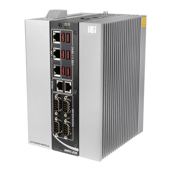
DRPC-230-ULT5 Embedded System 1.1 Overview Figure 1-1: DRPC-230-ULT5 Series ® The DRPC-230-ULT5 fanless embedded system is powered by the Intel Core™ i5-8365UE processor. It is designed for harsh environment applications, and supports DIN rail mounting method. The DRPC-230-ULT5 accepts a wide range of DC power input (12 V ~ 24 V), allowing it to be powered anywhere. -
Page 13: Model Variations
DRPC-230-ULT5 Embedded System 1.2 Model Variations The model variations of the DRPC-230-ULT5 are listed below. Model No. PCIe x4 Expansion Width DRPC-230-ULT5-i5/8G/S 81 mm Supports accelerator/PoE cards 127 mm DRPC-230-ULT5-i5/8G Table 1-1: DRPC-230-ULT5 Model Variations 1.3 Features The DRPC-230-ULT5 features are listed below: Fanless design ... -
Page 14: Front Panel
DRPC-230-ULT5 Embedded System 1.4 Front Panel The DRPC-230-ULT5 front panel contains: 3 x RJ-45 Gigabit LAN ports 4 x RS-232/422/485 serial ports (DB-9) 2 x RS-232 serial ports (RJ-45) 6 x USB 3.2 Gen 2 (10Gb/s) ports ... -
Page 15: Top Panel
DRPC-230-ULT5 Embedded System 1.5 Top Panel The DRPC-230-ULT5 top panel contains: 1 x 12 V ~ 24 V DC power terminal block 1 x Earth ground connector 1 x HDMI connector 1 x DisplayPort connector 1 x Power button ... -
Page 16: Technical Specifications
DRPC-230-ULT5 Embedded System 1.6 Technical Specifications The DRPC-230-ULT5 technical specifications are listed in Table 1-2. System ® CPU (SoC) Intel Core™ i5-8365UE processor (1.6 GHz, quad core, TDP=15W) Memory Two 260-pin 2400 MHz DDR4 SO-DIMM slots (pre-installed with one 8 GB memory module, system max. -
Page 17: Table 1-2: Technical Specifications
DRPC-230-ULT5 Embedded System Button/Switch Power button, Reset button, AT/ATX power switch Interior Expansion PCIe Mini 1 x Full-size (PCIe/USB 3.0/SATA) 1 x Full-size (USB 2.0, via PCIe x4 slot) 1 x M.2 2230 A-Key (PCIe/USB 2.0) 1 x M.2 2280 M-Key (PCIe x4, via PCIe x4 slot) Power Power Input One power connector (3-pin terminal block) -
Page 18: Dimensions
DRPC-230-ULT5 Embedded System 1.7 Dimensions The physical dimensions of the DRPC-230-ULT5 series are shown below. 1.7.1 DRPC-230-ULT5-i5/8G/S Dimensions Figure 1-4: DRPC-230-ULT5-i5/8G/S Dimensions (mm) Page 8... -
Page 19: Drpc-230-Ult5-I5/8G Dimensions
DRPC-230-ULT5 Embedded System 1.7.2 DRPC-230-ULT5-i5/8G Dimensions Figure 1-5: DRPC-230-ULT5-i5/8G Dimensions (mm) Page 9... -
Page 20: Unpacking
DRPC-230-ULT5 Embedded System Chapter Unpacking Page 10... -
Page 21: Anti-Static Precautions
DRPC-230-ULT5 Embedded System 2.1 Anti-static Precautions WARNING: Failure to take ESD precautions during installation may result in permanent damage to the DRPC-230-ULT5 and severe injury to the user. Electrostatic discharge (ESD) can cause serious damage to electronic components, including the DRPC-230-ULT5. Dry climates are especially susceptible to ESD. It is therefore critical that whenever the DRPC-230-ULT5 or any other electrical component is handled, the following anti-static precautions are strictly adhered to. -
Page 22: Packing List
DRPC-230-ULT5 Embedded System 2.3 Packing List NOTE: If some of the components listed in the checklist below are missing, please do not proceed with the installation. Contact the IEI reseller or vendor you purchased the DRPC-230-ULT5 from or contact an IEI sales representative directly. -
Page 23: Optional Items
DRPC-230-ULT5 Embedded System 2.4 Optional Items The following table lists the optional items that can be purchased separately. Optional Power adapter, 96 W (P/N: 63040-010096-230-RS) Power cable, DC jack to 3-pin terminal block, 200 mm (P/N: 32102-026500-100-RS) Wireless kit (P/N: EMB-WIFI-KIT01-R20) 20-pin Infineon TPM 2.0 module, software management tool, firmware v5.5 (P/N: TPM-IN02-R20) -
Page 24: Installation
DRPC-230-ULT5 Embedded System Chapter Installation Page 14... -
Page 25: Installation Precautions
DRPC-230-ULT5 Embedded System 3.1 Installation Precautions During installation, be aware of the precautions below: Read the user manual: The user manual provides a complete description of the DRPC-230-ULT5, installation instructions and configuration options. DANGER! Disconnect Power: Power to the DRPC-230-ULT5 must be ... -
Page 26: Internal Access Panel Removal
DRPC-230-ULT5 Embedded System Access can only be gained by SERVICE PERSONS or by USERS who have been instructed about the reasons for the restrictions applied to the location and about any precautions that shall be taken. Access is through the use of a TOOL or lock and key, or other means of ... -
Page 27: Hdd Installation
DRPC-230-ULT5 Embedded System 3.3 HDD Installation WARNING: Please install a solid state drive (SSD) when the DRPC-230-ULT5 is used in a harsh environment with extreme shock and vibration. The DRPC-230-ULT5 allows installation of one 2.5" HDD/SSD. To install a HDD into the system, please follow the steps below. -
Page 28: Pcie Mini Card Installation
DRPC-230-ULT5 Embedded System 3.4 PCIe Mini Card Installation The DRPC-230-ULT5 has one full-size PCIe Mini slot (MINI_PCIE1) on the motherboard for mSATA SSD or WWAN module installation. To install a full-size PCIe Mini module, follow the instructions below. Step 1: Remove the internal access panel from the DRPC-230-ULT5. -
Page 29: Figure 3-5: Inserting The Pcie Mini Card Into The Slot At An Angle
DRPC-230-ULT5 Embedded System Step 4: Line up the notch on the card with the notch on the slot. Slide the PCIe Mini card into the socket at an angle of about 20º (Figure 3-5). Figure 3-5: Inserting the PCIe Mini Card into the Slot at an Angle Step 5: Secure the PCIe Mini card with the retention screw previously removed (Figure 3-6). -
Page 30: Pcie Mini Card Slot Pinouts (Mini_Pcie1)
DRPC-230-ULT5 Embedded System 3.4.1 PCIe Mini Card Slot Pinouts (MINI_PCIE1) The MINI_PCIE1 slot supports USB, SATA and PCIe signal for installing mSATA or WWAN modules. PIN NO. DESCRIPTION PIN NO. DESCRIPTION PCIE_WAKE# VCC3 1.5V UIM_PWR UIM_DATA PCIE_CLK# UIM_CLK PCIE_CLK UIM_RST UIM_VPP PCIRST# PCIE_RXN... -
Page 31: Sim Card Installation
DRPC-230-ULT5 Embedded System 3.5 SIM Card Installation NOTE: A WWAN module must be installed in the PCIe Mini slot (MINI_PICE1) to provide WWAN communication. To install a SIM card, please follow the steps below. Step 1: Locate the SIM card slot (Figure 3-7). Figure 3-7: Unlock SIM Card Slot Cover Step 2: Unlock the SIM card slot cover by sliding the cover in the direction as shown by... -
Page 32: Figure 3-9: Sim Card Installation
DRPC-230-ULT5 Embedded System Step 3: Open the slot cover and place a SIM card onto the slot. The cut mark on the corner should be facing away from the slot as shown in Figure 3-9. Figure 3-9: SIM Card Installation Step 4: Close the slot cover and lock it by sliding it in the direction as shown by the arrow in Figure 3-10. -
Page 33: Module Installation
DRPC-230-ULT5 Embedded System 3.6 M.2 Module Installation The DRPC-230-ULT5 has one M.2 2230 A-key slot on the motherboard. To install a M.2 module, follow the instructions below. Step 1: Remove the internal access panel from the DRPC-230-ULT5. See Section 3.2. Step 2: Locate the M.2 slot on the motherboard (Figure 3-11). -
Page 34: Module Slot Pinouts (M2_A1)
DRPC-230-ULT5 Embedded System Step 4: Secure the M.2 module with the retention screw removed previously (Figure 3-13). Figure 3-13: Securing the M.2 Module 3.6.1 M.2 Module Slot Pinouts (M2_A1) The M2_A1 slot supports USB 2.0 and PCIe signal for installing a variety of M.2 2230 A-key modules. -
Page 35: Table 3-2: M.2 Module Slot (M2_A1) Pinouts
DRPC-230-ULT5 Embedded System PIN NO. DESCRIPTION PIN NO. DESCRIPTION PCIE_TX0+ PCIE_TX0- PCIE_RX0+ PCIE_RX0- CLK_PCIE0+ CLK_PCIE0- BUF_PLT_RST# PCIE_CLKREQ# Pull Up +V3.3A PCIE_WAKE# Pull Up +V3.3A +V3.3A +V3.3A Table 3-2: M.2 Module Slot (M2_A1) Pinouts Page 25... -
Page 36: Rs-232/422/485 Serial Port Connection
DRPC-230-ULT5 Embedded System 3.7 RS-232/422/485 Serial Port Connection The DRPC-230-ULT5 has four D-sub 9 male connectors for RS-232/422/485 connection. The pinouts of the D-sub 9 connectors are listed below. The RS-232/422/485 mode can be configured through BIOS (refer to Section 5.3.7); the default setting is RS-232 mode. PIN NO. -
Page 37: Lan Connection
DRPC-230-ULT5 Embedded System 3.9 LAN Connection The LAN connectors allow connection to an external network. Description Description LAN_MDI0P LAN_MDI2P LAN_MDI0N LAN_MDI2N LAN_MDI1P LAN_MDI3P LAN_MDI1N LAN_MDI3N Table 3-5: LAN Pinouts Figure 3-14: RJ-45 Ethernet Connector The RJ-45 Ethernet connector has two status LEDs, one green and one yellow. The green LED indicates activity on the port and the yellow LED indicates the port is linked. -
Page 38: At/Atx Mode Selection
DRPC-230-ULT5 Embedded System 3.10 AT/ATX Mode Selection AT and ATX power modes can both be used on the DRPC-230-ULT5. The selection is made through an AT/ATX switch on the top panel as shown below (Figure 3-15). Figure 3-15: AT/ATX Switch Location Page 28... -
Page 39: Din Rail Mounting
DRPC-230-ULT5 Embedded System 3.11 DIN Rail Mounting To mount the DRPC-230-ULT5 onto a DIN rail, please follow the steps below. Step 1: Prepare the DIN rail mounting bracket by sliding the small metal block into the slot of the bracket as shown below. Figure 3-16: DIN Rail Mounting Bracket Preparation Step 2: Attach the mounting bracket to the rear panel of the DRPC-230-ULT5. -
Page 40: Figure 3-18: Attach The Mounting Bracket To The Din Rail
DRPC-230-ULT5 Embedded System NOTE: In the diagrams below, the DIN rail is already installed on a surface or on a chassis. Step 3: Attach the upper edge of the mounting bracket to the DIN rail as shown in Figure 3-18. Figure 3-18: Attach the Mounting Bracket to the DIN Rail Step 4: Use a screwdriver to rotate the screw of the mounting bracket until the small... -
Page 41: Power -O N Procedure
DRPC-230-ULT5 Embedded System 3.12 Power-On Procedure 3.12.1 Installation Checklist WARNING: Make sure a power supply with the correct input voltage is being fed into the system. Incorrect voltages applied to the system may cause damage to the internal electronic components and may also cause injury to the user. To power on the embedded system please make sure of the following: The internal access panel is installed ... -
Page 42: Power-On Procedure
DRPC-230-ULT5 Embedded System 3.12.3 Power-on Procedure To power-on the DRPC-230-ULT5 please follow the steps below: Step 1: Connect the power source to the power input terminal block. Step 2: Use the M4*6 screw that came with the package to secure the grounding cable with the grounding connector on the top panel of the DRPC-230-ULT5. -
Page 43: Available Drivers
DRPC-230-ULT5 Embedded System 3.13 Available Drivers All the drivers for the DRPC-230-ULT5 are available on IEI Resource Download Center (https://download.ieiworld.com). Type DRPC-230-ULT5 and press Enter to find all the relevant software, utilities, and documentation. Figure 3-21: IEI Resource Download Center 3.13.1 Driver Download To download drivers from IEI Resource Download Center, follow the steps below. - Page 44 DRPC-230-ULT5 Embedded System Step 3: Click the driver file name on the page and you will be prompted with the following window. You can download the entire ISO file ( ), or click the small arrow to find an individual driver and click the file name to download ( ...
-
Page 45: Troubleshooting And Maintenance
DRPC-230-ULT5 Embedded System Chapter Troubleshooting and Maintenance Page 35... -
Page 46: System Maintenance Overview
DRPC-230-ULT5 Embedded System WARNING: Take Anti-Static precautions whenever maintenance is being carried out on the system components. Failure to take anti-static precautions can cause permanent system damage. For more details on anti-static precautions, please refer to Section 2.1. 4.1 System Maintenance Overview NOTE: When doing maintenance operations on the system, please follow the instructions in this chapter. -
Page 47: The System Doesn't Boot Up
DRPC-230-ULT5 Embedded System Step 3: Make sure the power button is turned on. Step 4: Plug the system into a monitor and check to see if anything appears on the screen. If the boot-up screen appears it means the power LED has failed. To fix this problem, contact an IEI sales representative directly. -
Page 48: Clear Cmos
DRPC-230-ULT5 Embedded System Step 3: Make the jumper settings in accordance with the settings described and defined in the following sections. Step 0: 4.3.1 Clear CMOS If the DRPC-230-ULT5 fails to boot due to improper BIOS settings, the clear CMOS button clears the CMOS data and resets the system BIOS information. -
Page 49: Me Override Jumper
DRPC-230-ULT5 Embedded System 4.3.2 ME Override Jumper The ME Override jumper (ME_FLASH1) allows users to enable or disable the ME firmware update. Refer to Figure 4-2 and Table 4-1 for the jumper location and settings. Setting Description Open Disabled (default) Short Enabled Table 4-1: ME Override Jumper Settings... -
Page 50: Bios
DRPC-230-ULT5 Embedded System Chapter BIOS Page 40... -
Page 51: Introduction
DRPC-230-ULT5 Embedded System 5.1 Introduction The BIOS is programmed onto the BIOS chip. The BIOS setup program allows changes to certain system settings. This chapter outlines the options that can be changed. NOTE: Some of the BIOS options may vary throughout the life cycle of the product and are subject to change without prior notice. -
Page 52: Getting Help
DRPC-230-ULT5 Embedded System Function Decrease the numeric value or make changes Esc key Main Menu – Quit and not save changes into CMOS Status Page Setup Menu and Option Page Setup Menu -- Exit current page and return to Main Menu F1 key General help, only for Status Page Setup Menu and Option Page Setup Menu... -
Page 53: Main
DRPC-230-ULT5 Embedded System The following sections completely describe the configuration options found in the menu items at the top of the BIOS screen and listed above. 5.2 Main The Main BIOS menu (BIOS Menu 1) appears when the BIOS Setup program is entered. The Main menu gives an overview of the basic system information. -
Page 54: Advanced
DRPC-230-ULT5 Embedded System The System Overview field has two user configurable fields: System Date [xx/xx/xx] Use the System Date option to set the system date. Manually enter the day, month and year. System Time [xx:xx:xx] Use the System Time option to set the system time. Manually enter the hours, minutes and seconds. -
Page 55: Cpu Configuration
DRPC-230-ULT5 Embedded System 5.3.1 CPU Configuration Use the CPU Configuration menu (BIOS Menu 3) to view detailed CPU specifications and configure the CPU. Aptio Setup Utility – Copyright (C) 2019 American Megatrends, Inc. Advanced CPU Configuration When enabled, a VMM can utilize the additional Type Intel(R) Core(TM) - Page 56 DRPC-230-ULT5 Embedded System Active Processor Cores [All] Use the Active Processor Cores BIOS option to enable numbers of cores in the processor package. Enable all cores in the processor package. EFAULT Enable one core in the processor package. ...
-
Page 57: Pch-Fw Configuration
DRPC-230-ULT5 Embedded System 5.3.2 PCH-FW Configuration The PCH-FW Configuration menu (BIOS Menu 4) allows Intel® Active Management Technology (AMT) options to be configured. Aptio Setup Utility – Copyright (C) 2019 American Megatrends, Inc. Advanced AMT BIOS Features [Enabled] When disabled AMT BIOS Unconfigure ME [Disabled] Features are no longer... -
Page 58: Ptt Configuration
DRPC-230-ULT5 Embedded System 5.3.2.1 PTT Configuration Use the PTT Configuration menu (BIOS Menu 5) to configure settings related to the Trusted Platform Module (TPM). Aptio Setup Utility – Copyright (C) 2019 American Megatrends, Inc. Advanced PTT Capability / State Select TPM device: PTT or dTPM. -
Page 59: Trusted Computing
DRPC-230-ULT5 Embedded System 5.3.3 Trusted Computing Use the Trusted Computing menu (BIOS Menu 6) to configure settings related to the Trusted Computing Group (TCG) Trusted Platform Module (TPM). Aptio Setup Utility – Copyright (C) 2019 American Megatrends, Inc. Advanced Configuration Enables or Disables BIOS Security Device Support [Disable]... -
Page 60: Acpi Settings
DRPC-230-ULT5 Embedded System 5.3.4 ACPI Settings The ACPI Settings menu (BIOS Menu 7) configures the Advanced Configuration and Power Interface (ACPI) options. Aptio Setup Utility – Copyright (C) 2019 American Megatrends, Inc. Advanced ACPI Settings Select the highest ACPI sleep state the system ACPI Sleep State [S3 (Suspend to RAM] will enter when the... -
Page 61: Rtc Wake Settings
DRPC-230-ULT5 Embedded System 5.3.5 RTC Wake Settings The RTC Wake Settings menu (BIOS Menu 8) configures RTC wake event. Aptio Setup Utility – Copyright (C) 2019 American Megatrends, Inc. Advanced Wake system with Fixed Time [Disabled] Enable or disable System wake on alarm event. -
Page 62: Iwdd H/W Monitor
DRPC-230-ULT5 Embedded System Wake up second After setting the alarm, the computer turns itself on from a suspend state when the alarm goes off. 5.3.6 iWDD H/W Monitor The iWDD H/W Monitor menu (BIOS Menu 9) contains the fan configuration submenus and displays operating temperature, fan speeds and system voltages. -
Page 63: Smart Fan Mode Configuration
DRPC-230-ULT5 Embedded System +VDDQ +V1.05A +VCCSA +3.3V +3.3VSB 5.3.6.1 Smart Fan Mode Configuration Use the Smart Fan Mode Configuration submenu (BIOS Menu 10) to configure fan temperature and speed settings. Aptio Setup Utility – Copyright (C) 2019 American Megatrends, Inc. Advanced Smart Fan Mode Configuration Smart Fan Mode Select... - Page 64 DRPC-230-ULT5 Embedded System Auto Mode The fan adjusts its speed using these EFAULT settings: Auto mode fan start temperature Auto mode fan off temperature Auto mode fan start PWM Auto mode fan slope PWM Auto mode fan start temperature [40] ...
-
Page 65: F81866 Super Io Configuration
DRPC-230-ULT5 Embedded System fan off temperature, the fan speed change to be lowest. To set a value, select the Auto mode fan off temperature option and enter a decimal number between 1 and 100. Auto mode fan start PWM [30] ... -
Page 66: Serial Port N Configuration
DRPC-230-ULT5 Embedded System 5.3.7.1 Serial Port n Configuration Use the Serial Port n Configuration menu (BIOS Menu 12) to configure the serial port n. Aptio Setup Utility – Copyright (C) 2019 American Megatrends, Inc. Advanced Serial Port 1 Configuration Enable or Disable Serial Port (COM) Serial Port [Enabled]... -
Page 67: Serial Port Console Redirection
DRPC-230-ULT5 Embedded System 5.3.8 Serial Port Console Redirection The Serial Port Console Redirection menu (BIOS Menu 13) allows the console redirection options to be configured. Console redirection allows users to maintain a system remotely by re-directing keyboard input and text output through the serial port. Aptio Setup Utility –... -
Page 68: Legacy Console Redirection Settings
DRPC-230-ULT5 Embedded System Console Redirection [Disabled] Use Console Redirection option to enable or disable the console redirection function. Disabled Disabled the console redirection function EFAULT Enabled Enabled the console redirection function 5.3.8.1 Legacy Console Redirection Settings The Legacy Console Redirection Settings menu (BIOS Menu 14) allows the legacy console redirection options to be configured. -
Page 69: Console Redirection Settings
DRPC-230-ULT5 Embedded System COM6 COM7 (Pci Bus0, Dev0, Func0) (Disabled) 5.3.8.2 Console Redirection Settings The Console Redirection Settings menu (BIOS Menu 15) allows the console redirection options to be configured. The option is active when Console Redirection option is enabled. Aptio Setup Utility –... - Page 70 DRPC-230-ULT5 Embedded System Bits per second [115200] Use the Bits per second option to specify the serial port transmission speed. The speed must match the other side. Long or noisy lines may require lower speeds. 9600 Sets the serial port transmission speed at 9600. ...
-
Page 71: Usb Configuration
DRPC-230-ULT5 Embedded System Stop Bits [1] Use the Stop Bits option to specify the number of stop bits used to indicate the end of a serial data packet. Communication with slow devices may require more than 1 stop bit. ... -
Page 72: Csm Configuration
DRPC-230-ULT5 Embedded System USB drivers loaded. When this option is enabled, any attached USB mouse or USB keyboard can control the system even when there is no USB driver loaded onto the system. Enabled Legacy USB support enabled EFAULT ... -
Page 73: Nvme Configuration
DRPC-230-ULT5 Embedded System 5.3.11 NVMe Configuration Use the NVMe Configuration (BIOS Menu 18) menu to display the NVMe controller and device information. Aptio Setup Utility – Copyright (C) 2018 American Megatrends, Inc. Advanced NVMe controller and Drive information No NVMe Device Found --------------------- : Select Screen ↑... -
Page 74: Iei Feature
DRPC-230-ULT5 Embedded System 5.3.12 IEI Feature Use the IEI Feature menu (BIOS Menu 19) to configure One Key Recovery function. Aptio Setup Utility – Copyright (C) 2019 American Megatrends, Inc. Advanced iEi Feature Auto Recovery Function Reboot and recover Auto Recovery Function [Disabled] system automatically within 10 min, when OS... -
Page 75: Chipset
DRPC-230-ULT5 Embedded System 5.4 Chipset Use the Chipset menu (BIOS Menu 20) to configure the system chipset. Aptio Setup Utility – Copyright (C) 2019 American Megatrends, Inc. Main Advanced Chipset Boot Security Save & Exit > System Agent (SA) Configuration System Agent (SA) >... -
Page 76: Memory Configuration
DRPC-230-ULT5 Embedded System VT-d [Disabled] Use the VT-d option to enable or disable VT-d support. Disabled Disable VT-d support. EFAULT Enabled Enable VT-d support. 5.4.1.1 Memory Configuration Use the Memory Configuration submenu (BIOS Menu 22) to display the memory information. -
Page 77: Graphics Configuration
DRPC-230-ULT5 Embedded System 5.4.1.2 Graphics Configuration Use the Graphics Configuration menu (BIOS Menu 23) to configure the graphics settings. Aptio Setup Utility – Copyright (C) 2019 American Megatrends, Inc. Chipset Graphics Configuration Select which of Auto/IGFX/PCIE Graphics Primary Display [Auto] device should be Primary Internal Graphics [Enabled]... - Page 78 DRPC-230-ULT5 Embedded System Enabled Enable the internal graphics device. The following EFAULT options/submenu appear with values that can be selected: DVMT Pre-Allocated DVMT Total Gfx Mem LCD Control DVMT Pre-Allocated [32M] Use the DVMT Pre-Allocated option to set the amount of system memory allocated to the integrated graphics processor when the system boots.
-
Page 79: Pch-Io Configuration
DRPC-230-ULT5 Embedded System 5.4.2 PCH-IO Configuration Use the PCH-IO Configuration menu (BIOS Menu 24) to configure the PCH-IO chipset. Aptio Setup Utility – Copyright (C) 2019 American Megatrends, Inc. Chipset PCH-IO Configuration Select AC power state when power is re-applied after Auto Power Button Status [Disable (ATX)] a power failure. - Page 80 DRPC-230-ULT5 Embedded System Power Saving Function(ERP) [Disabled] Use the Power Saving Function(ERP) BIOS option to enable or disable the power saving function. Disabled Power saving function is disabled. EFAULT Enabled Power saving function is enabled. It will reduce power consumption when the system is off.
-
Page 81: Pci Express Configuration
DRPC-230-ULT5 Embedded System 5.4.2.1 PCI Express Configuration Use the PCI Express Configuration submenu (BIOS Menu 25) to configure the PCI Express slots. Aptio Setup Utility – Copyright (C) 2019 American Megatrends, Inc. Chipset PCI Express Configuration PCI Express Root Port Settings. - Page 82 DRPC-230-ULT5 Embedded System M2_A1 / MINI_PCIE1 / PCIEX4_1 [Enabled] Use the M2_A1 / MINI_PCIE1 / PCIEX4_1 option to enable or disable the M.2, PCIe Mini or PCIe x4 expansion slots. Disabled Disables the expansion slot. Enabled Enables the expansion slot. EFAULT PCIe Speed [Auto] ...
-
Page 83: Sata And Rst Configuration
DRPC-230-ULT5 Embedded System 5.4.2.2 SATA And RST Configuration Use the SATA And RST Configuration menu (BIOS Menu 27) to change and/or set the configuration of the SATA devices installed in the system. Aptio Setup Utility – Copyright (C) 2019 American Megatrends, Inc. Advanced SATA And RST Configuration Enable or disable SATA... - Page 84 DRPC-230-ULT5 Embedded System SATA Mode Selection [AHCI] Use the SATA Mode Selection option to configure how the SATA controller(s) operate. AHCI Configures SATA devices as AHCI device. EFAULT Intel RST Configures SATA devices as RAID device. Premium with Intel Optane System...
-
Page 85: Security
DRPC-230-ULT5 Embedded System 5.5 Security Use the Security menu (BIOS Menu 28) to set system and user passwords. Aptio Setup Utility – Copyright (C) 2019 American Megatrends, Inc. Main Advanced Chipset Security Boot Save & Exit Password Description Set Administrator Password If ONLY the Administrator’s password is set, then this only limits access to Setup and is... -
Page 86: Boot
DRPC-230-ULT5 Embedded System 5.6 Boot Use the Boot menu (BIOS Menu 29) to configure system boot options. Aptio Setup Utility – Copyright (C) 2019 American Megatrends, Inc. Main Advanced Chipset Security Boot Save & Exit Boot Configuration Select the keyboard Bootup NumLock State [On] NumLock state... - Page 87 DRPC-230-ULT5 Embedded System Quiet Boot [Enabled] Use the Quiet Boot BIOS option to select the screen display when the system boots. Disabled Normal POST messages displayed Enabled OEM Logo displayed instead of POST messages EFAULT Launch PXE OpROM [Disabled] ...
-
Page 88: Save & Exit
DRPC-230-ULT5 Embedded System 5.7 Save & Exit Use the Save & Exit menu (BIOS Menu 30) to load default BIOS values, optimal failsafe values and to save configuration changes. Aptio Setup Utility – Copyright (C) 2019 American Megatrends, Inc. Main Advanced Chipset Security... - Page 89 DRPC-230-ULT5 Embedded System Save as User Defaults Use the Save as User Defaults option to save the changes done so far as user defaults. Restore User Defaults Use the Restore User Defaults option to restore the user defaults to all the setup options. Page 79...
-
Page 90: Interface Connectors
DRPC-230-ULT5 Embedded System Chapter Interface Connectors Page 80... -
Page 91: Peripheral Interface Connectors
DRPC-230-ULT5 Embedded System 6.1 Peripheral Interface Connectors The DRPC-230-ULT5 embedded system motherboard comes with a number of peripheral interface connectors and configuration jumpers. The connector locations are shown in Table 6-1. The Pin 1 locations of the on-board connectors are also indicated in the diagrams. -
Page 92: Internal Peripheral Connectors
DRPC-230-ULT5 Embedded System 6.2 Internal Peripheral Connectors Internal peripheral connectors on the motherboard and are only accessible when the motherboard is outside of the chassis. The table below shows a list of the connectors on the motherboard. Pinouts of these connectors can be found in the following sections. Connector Type Label... -
Page 93: Digital I/O Connector (Dio1)
DRPC-230-ULT5 Embedded System 6.2.2 Digital I/O Connector (DIO1) PIN NO. DESCRIPTION Output 3 Output 2 Output 1 Output 0 Input 3 Input 2 Input 1 Input 0 Table 6-3: Digital I/O Connector (DIO1) Pinouts 6.2.3 Fan Connectors (CPU/FAN1, CPU/FAN2) PIN NO. DESCRIPTION +V12S Rotation Signal... -
Page 94: Sata Connector (Sata1)
DRPC-230-ULT5 Embedded System 6.2.5 SATA Connector (SATA1) PIN NO. DESCRIPTION PIN NO. DESCRIPTION +V5S SATA_RX+ SATA_RX- +V5S +V5S SATA_TX- +V5S SATA_TX+ +V5S Table 6-6: SATA 6Gb/s Connector (SATA1) Pinouts 6.2.6 SMBus Connector (SMB1) PIN NO. DESCRIPTION SMBus (I C) Data SMBus (I C) CLK Table 6-7: SMBus Connector (SMB1) Pinouts... -
Page 95: Tpm Connector (Tpm1)
DRPC-230-ULT5 Embedded System 6.2.8 TPM Connector (TPM1) PIN NO. DESCRIPTION PIN NO. DESCRIPTION SPI_TPM_CS0# PM_RSTRSM# SPI_TPM_CLK Pull High SPI_TPM_SO SPI_TPM_HOLD# SPI_TPM_SI SPI_TPM_CS2# SPI_TPM_WP SPI_TPM_INT# +3.3V+TPM PCIE_RST# Table 6-9: TPM Connector (TPM1) Pinouts 6.2.9 USB DOM Connector (DOM1) PIN NO. DESCRIPTION PIN NO. -
Page 96: A Regulatory Compliance
DRPC-230-ULT5 Embedded System Appendix Regulatory Compliance Page 86... - Page 97 DRPC-230-ULT5 Embedded System DECLARATION OF CONFORMITY This equipment is in conformity with the following EU directives: EMC Directive 2014/30/EU Low-Voltage Directive 2014/35/EU RoHS II Directive 2015/863/EU If the user modifies and/or install other devices in the equipment, the CE conformity declaration may no longer apply.
- Page 98 DRPC-230-ULT5 Embedded System Español [Spanish] IEI Integration Corp declara que el equipo cumple con los requisitos esenciales y cualesquiera otras disposiciones aplicables o exigibles de la Directiva 1999/5/CE. Ελληνική [Greek] IEI Integration Corp ΔΗΛΩΝΕΙ ΟΤΙ ΕΞΟΠΛΙΣΜΟΣ ΣΥΜΜΟΡΦΩΝΕΤΑΙ ΠΡΟΣ ΤΙΣ ΟΥΣΙΩΔΕΙΣ ΑΠΑΙΤΗΣΕΙΣ ΚΑΙ ΤΙΣ ΛΟΙΠΕΣ ΣΧΕΤΙΚΕΣ ΔΙΑΤΑΞΕΙΣ ΤΗΣ ΟΔΗΓΙΑΣ 1999/5/ΕΚ.
- Page 99 DRPC-230-ULT5 Embedded System Româna [Romanian] IEI Integration Corp declară că acest echipament este in conformitate cu cerinţele esenţiale şi cu celelalte prevederi relevante ale Directivei 1999/5/CE. Slovensko [Slovenian] IEI Integration Corp izjavlja, da je ta opreme v skladu z bistvenimi zahtevami in ostalimi relevantnimi določili direktive 1999/5/ES.
- Page 100 DRPC-230-ULT5 Embedded System FCC WARNING This equipment complies with Part 15 of the FCC Rules. Operation is subject to the following two conditions: This device may not cause harmful interference, and This device must accept any interference received, including interference that ...
-
Page 101: B Safety Precautions
DRPC-230-ULT5 Embedded System Appendix Safety Precautions Page 91... -
Page 102: Safety Precautions
DRPC-230-ULT5 Embedded System B.1 Safety Precautions WARNING: The precautions outlined in this appendix should be strictly followed. Failure to follow these precautions may result in permanent damage to the DRPC-230-ULT5. Please follow the safety precautions outlined in the sections that follow: B.1.1 General Safety Precautions Please ensure the following safety precautions are adhered to at all times. -
Page 103: Anti-Static Precautions
DRPC-230-ULT5 Embedded System B.1.2 Anti-static Precautions WARNING: Failure to take ESD precautions during the installation of the DRPC-230-ULT5 result permanent damage DRPC-230-ULT5 and severe injury to the user. Electrostatic discharge (ESD) can cause serious damage to electronic components, including the DRPC-230-ULT5. Dry climates are especially susceptible to ESD. It is therefore critical that whenever the DRPC-230-ULT5 is opened and any of the electrical components are handled, the following anti-static precautions are strictly adhered to. -
Page 104: Product Disposal
DRPC-230-ULT5 Embedded System B.1.4 Product Disposal CAUTION: Risk of explosion if the battery is replaced by an incorrect type; Replacement of a battery with an incorrect type that can defeat a safeguard (for example, in the case of some lithium battery types); Disposal of a battery into fire or a hot oven, or mechanically crushing or cutting of a battery, that can result in an explosion;... -
Page 105: Maintenance And Cleaning Precautions
DRPC-230-ULT5 Embedded System B.2 Maintenance and Cleaning Precautions When maintaining or cleaning the DRPC-230-ULT5, please follow the guidelines below. B.2.1 Maintenance and Cleaning Prior to cleaning any part or component of the DRPC-230-ULT5, please read the details below. The interior of the DRPC-230-ULT5 does not require cleaning. Keep fluids ... -
Page 106: C Digital I/O Interface
DRPC-230-ULT5 Embedded System Appendix Digital I/O Interface Page 96... - Page 107 DRPC-230-ULT5 Embedded System The DIO connector on the DRPC-230-ULT5 is interfaced to GPIO ports on the Super I/O chipset. The DIO has both 8-bit digital inputs and 8-bit digital outputs. The digital inputs and digital outputs are generally control signals that control the on/off circuit of external devices or TTL devices.
- Page 108 DRPC-230-ULT5 Embedded System AH – 6FH Sub-function: AL – 9 :Set the digital port as OUTPUT :Digital I/O output value Assembly Language Sample 2 AX, 6F09H ;setting the digital port as output BL, 09H ;digital value is 09H Digital Output is 1001b Page 98...
-
Page 109: D Watchdog Timer
DRPC-230-ULT5 Embedded System Appendix Watchdog Timer Page 99... - Page 110 DRPC-230-ULT5 Embedded System NOTE: The following discussion applies to DOS. Contact IEI support or visit the IEI website for drivers for other operating systems. The Watchdog Timer is a hardware-based timer that attempts to restart the system when it stops working. The system may stop working because of external EMI or software bugs. The Watchdog Timer ensures that standalone systems like ATMs will automatically attempt to restart in the case of system problems.
- Page 111 DRPC-230-ULT5 Embedded System NOTE: The Watchdog Timer is activated through software. The software application that activates the Watchdog Timer must also deactivate it when closed. If the Watchdog Timer is not deactivated, the system will automatically restart after the Timer has finished its countdown. EXAMPLE PROGRAM: ;...
-
Page 112: E Error Beep Code
DRPC-230-ULT5 Embedded System Appendix Error Beep Code Page 102... -
Page 113: Pei Beep Codes
DRPC-230-ULT5 Embedded System E.1 PEI Beep Codes Number of Beeps Description Memory not Installed Memory was installed twice (InstallPeiMemory routine in PEI Core called twice) Recovery started DXEIPL was not found DXE Core Firmware Volume was not found Recovery failed S3 Resume failed Reset PPI is not available E.2 DXE Beep Codes... -
Page 114: F Hazardous Materials Disclosure
DRPC-230-ULT5 Embedded System Appendix Hazardous Materials Disclosure Page 104... -
Page 115: Rohs Ii Directive (2015/863/Eu)
DRPC-230-ULT5 Embedded System F.1 RoHS II Directive (2015/863/EU) The details provided in this appendix are to ensure that the product is compliant with the RoHS II Directive (2015/863/EU). The table below acknowledges the presences of small quantities of certain substances in the product, and is applicable to RoHS II Directive (2015/863/EU). -
Page 116: China Rohs
DRPC-230-ULT5 Embedded System F.2 China RoHS 此附件旨在确保本产品符合中国 RoHS 标准。以下表格标示此产品中某有毒物质的含量符 合中国 RoHS 标准规定的限量要求。 本产品上会附有”环境友好使用期限”的标签,此期限是估算这些物质”不会有泄漏或突变”的 年限。本产品可能包含有较短的环境友好使用期限的可替换元件,像是电池或灯管,这些 元件将会单独标示出来。 部件名称 有毒有害物质或元素 壳体 显示 印刷电路板 金属螺帽 电缆组装 风扇组装 电力供应组装 电池 O: 表示该有毒有害物质在该部件所有物质材料中的含量均在 SJ/T11364-2014 與 GB/T26572-2011 标准规定的限量要求以下。 X: 表示该有毒有害物质至少在该部件的某一均质材料中的含量超出 SJ/T11364-2014 與 GB/T26572-2011 标准规定的限量要求。 Page 106...
Need help?
Do you have a question about the DRPC-230-ULT5 Series and is the answer not in the manual?
Questions and answers