Table of Contents

Related Manuals for Brandywine PDU-240


Summary of Contents for Brandywine PDU-240
- Page 1 User Guide Pulse Distribution Unit Model PDU-240 P/N 018000501 Revision B June 2017 Brandywine Communications 1153 Warner Avenue Tustin, CA 92780 (714) 755 1050 (714) 755 0175 http://www.brandywinecomm.com/ MANUAL P/N 900000154 REV A...
- Page 2 Revision History REVISION DATE COMMENTS 5-20-2016 Original release of PDU-240 user guide. 9-21-2017 Added information on fuse replacement MANUAL P/N 900000154 REV B...
- Page 3 Safety Warnings WARNING: This unit contains lethal AC voltages. Disconnect the unit from the AC supply before removing the cover. WARNING: The lightning flash with an arrowhead inside of an equilateral triangle is intended to alert the user to the presence of un-insulated “dangerous voltage”...
-
Page 4: Table Of Contents
3.1 Unpacking....................9 3.2 Installation....................9 3.3 Connections.................... 10 3.3.1 Alarm Input Connection..............10 4 Operation.......................11 4.1 Powering the PDU-240 ................11 4.2 Selecting the Input Reference..............11 4.3 Fault Indicator ..................11 5 Maintenance and Troubleshooting ..............12 6 Calibration .....................13 7 Drawings .......................14... -
Page 5: Specifications
Specifications Inputs 1.1.1 Reference Pulse Input Pulse: 1 PPS through 10Mhz Input Levels o 1 level : 2.5V min, 10.5V max o 0 level : 0.25V max Input Impedance: 50 ohm or 10k ohm. Settable by link, see figure 1 ... -
Page 6: Outputs
Outputs 1.2.1 Reference Pulse Output Number of Outputs: 24 Connector Type: BNC Output Protection: short circuit proof Output Level: o 1 level: 5V±5% into 50 ohms (10V ±5% settable with link) o Optional 1 level: 2.5V into 50 ohm o 0 level: 0.25V max into 50 ohm ... -
Page 7: Switches And Indicators
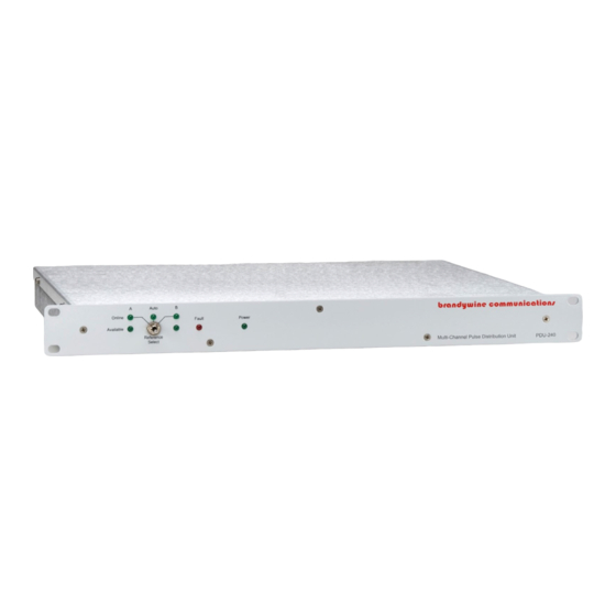
Switches and Indicators 1.3.1 Status LED Indicators Power (Green) Reference Input A Available (Green) Reference Input A Online (Green) Reference Input B Available (Green) Reference Input B Online (Green) lAutomatic Reference Selection Selected (Green) ... -
Page 8: Option Configuration Sheet
Option Configuration Sheet Configuration Options Part Number Base Unit 2 switched input 24 output 10V level 018000501 2 switched input 24 output 5V levels 018000502 2 switched input 24 output 3.3V levels 018000503 2 independent input 12 output 018000504 Group 1 10V Group 2 10V 2 independent input 12 output 018000505... -
Page 9: Unpacking And Installation
1 power cord 1 user guide Note the power entry module on the rear of the PDU-240 chassis. Please take note of the voltage displayed on the rear of the power entry module and verify that the voltage matches the local line’s voltage. -
Page 10: Connections
1 PPS input signals may be present. The factory standard PDU-240 configuration is a logic HI signal on the ALARM IN pin indicating that the input is GOOD. A built in pull-up resistor ensures that if no ALARM IN connection is made the reference is considered good. -
Page 11: Operation
Refer to Figure 1 for a guide of the front panel controls and indicators. Powering the PDU-240 Once all connections to the PDU-240 have been made, apply power to the unit by placing the on/off switch to the on position. The on/off switch is located on the rear panel power entry module. -
Page 12: Maintenance And Troubleshooting
Maintenance and Troubleshooting There is no preventive maintenance required for the PDU-240. SYMPTOM POTENTIAL CAUSE CORRECTIVE ACTION No signal 1. There is no input 1. Connect the reference outputs reference. input. 2. The Reference Select 2. Set the selector switch to... -
Page 13: Calibration
The pulse counter MUST be configured to use an external reference such as a Cesium, Rubidium, or GPS disciplined OCXO as its time-base. The calibration accuracy of the PDU-240 can only be as accurate as the reference against which it is calibrated. It should be better than 1x10... -
Page 14: Drawings
Drawings FIGURE DESCRIPTION PDU-240 Front Panel PDU-240 Rear Panel PDU-240 Mechanical Outline PDU-240 Link Location MANUAL P/N 900000154 REV B...
Need help?
Do you have a question about the PDU-240 and is the answer not in the manual?
Questions and answers