Table of Contents
Advertisement
Quick Links
Advertisement
Table of Contents

Related Manuals for Brandywine TDU-310


Summary of Contents for Brandywine TDU-310
- Page 1 User Guide Multi-Channel Time Distribution Unit Model TDU-310 P/N 018000001 Revision G November 2018 Brandywine Communications 1153 Warner Avenue Tustin, CA 92780 (714) 755 1050 (714) 755 0175 http://www.brandywinecomm.com MANUAL P/N 900000019 REV G...
- Page 2 Initial release of TDU-310 user guide. 12-06-04 Revision of entire TDU-310 user guide. 02-21-06 Customer’s comments incorporated into TDU-310 user guide. 02-01-08 Revised input and output configuration tables to reflect correct factory jumper settings. Outline drawing updated to Rev B, showing rounded corners on front panel.
- Page 3 Safety Warnings WARNING: To prevent fire and electric shock, do not expose this unit to rain or moisture. WARNING: The lightning flash with an arrowhead inside of an equilateral triangle is intended to alert the user to the presence of un-insulated “dangerous voltage”...
-
Page 4: Table Of Contents
Outputs .................... 7 Controls and Indicators ................8 Installation ...................... 9 Scope of Section ..................9 Unpacking and Inspection ..............9 TDU-310 Configuration ................9 2.3.1 Internal Jumper Settings ............... 10 2.3.2 Output Jumper Settings ..............11 Installation and Testing ................. 12 Operating Instructions .................. -
Page 5: Introduction
1 input (HaveQuick), Time Code 2 input (50 bit/second BCD), and the state change of the Time Fault Discrete input. The TDU-310 is designed to provide dual redundant timing signals for use in telecommunications, power utilities, and military communication applications. -
Page 6: Specification
Specification 1.3.1 Inputs INPUT SIGNAL LEVEL IMPEDANCE CONNECTOR Reference A 1 PPS 0 V to +5 VDC or 50 ohms Inputs 0 VDC to 10 VDC and positive on time Time Code 1 0 V to +5 VDC 50 ohms (HaveQuick) Time Code 2 RS232 or RS422... -
Page 7: Outputs
1.3.2 Outputs OUTPUT SIGNAL LEVEL IMPEDANCE RISE CONNECTOR TIME GROUP 1 PULSE 0-10 V LOW Z OR 50 OHMS < 10 ns J9, J11, J13, J15, 0-pk TIME CODE 1 (HQ) LINK SELECTABLE AND J17 TIME CODE 2 (BCD) PER OUTPUT LINK SELECTABLE GROUP 2 PULSE... -
Page 8: Controls And Indicators
Controls and Indicators All operating controls excluding the power control are located on the front panel of the TDU-310. CONTROL FUNCTION Reference Select Manual selection of the input source. Either Reference A, Reference B, or automatic selection. Power Located on the rear panel of the unit. -
Page 9: Installation
The TDU-310 occupies 1U (1.75 inches) of vertical cabinet space. TDU-310 Configuration Refer to Figure 6.4 for the locations of the push on jumper links. The TDU-310 is extremely flexible with respect to the input and output configurations. Setup is done using the push on jumpers on the main printed circuit board assembly. -
Page 10: Internal Jumper Settings
Internal Jumper Settings 2.3.1 Jumper Connector Printed Circuit Card Jumper Top or Bottom Function Left or Right No 1PPS Channel A No 1PPS No 1PPS Channel B No 1PPS No Have Quick Channel A No HQ No Have Quick Channel B No HQ RS422 or RS232 RS232... -
Page 11: Output Jumper Settings
2.3.2 Output Jumper Settings Link Connector Output 1 Level Impedance (Typical) Link in/out Link in/out LK27 10V/5V LoZ/50Ω LK28 10V/5V LoZ/50Ω LK29 10V/5V LoZ/50Ω LK30 10V/5V LoZ/50Ω LK31 10V/5V LoZ/50Ω LK32 10V/5V LoZ/50Ω LK33 10V/5V LoZ/50Ω LK34 10V/5V LoZ/50Ω LK35 10V/5V LoZ/50Ω... -
Page 12: Installation And Testing
Connect the AC power source to the TDU-310. Apply power to the unit by switching on the power switch located on the rear panel of the unit. -
Page 13: Operating Instructions
Time Code 2 (BCD)) OR the Time Fault Discrete line is pulled low. If any of these conditions is met, the TDU-310 will switch ALL outputs to be driven from the Reference B input. If both Reference A AND Reference B are faulty, the outputs will be switched to Reference A. -
Page 14: Link Locations And Pin Assignments
Link Locations and Pin Assignments Scope of Section Section 4 provides the link locations and the input/output pin assignments for the TDU-310. Link Locations Refer to Figure 6.4 for the locations of the push on jumper links. Pin Assignments 4.3.1... -
Page 15: Pin Assignments
4.3.3 Pin Assignments CONNECTOR CONNECTOR CONNECTOR SIGNAL REFERENCE TYPE DB-9 MALE REFERENCE A TIME FAULT DISCRETE GROUND GROUND TIME CODE 2 INPUT RS232 TIME CODE 2 INPUT RS422 (–) TIME CODE 2 INPUT RS422 (+) DB-9 MALE REFERENCE B TIME FAULT DISCRETE GROUND GROUND TIME CODE 2 INPUT RS232... -
Page 16: Maintenance And Calibration
Preventative maintenance can therefore be restricted to a regular inspection of the status indicators. WARNING: Before removing the TDU-310 cover make sure that the power cord has been detached from the rear panel of the unit. Fault Finding... -
Page 17: Drawings
Drawings FIGURE DESCRIPTION TDU-310 Front Panel TDU-310 Rear Panel TDU-310 Mechanical Outline TDU-310 Link Location Table 10 TDU-310 Drawings MANUAL P/N 900000019 REV G... -
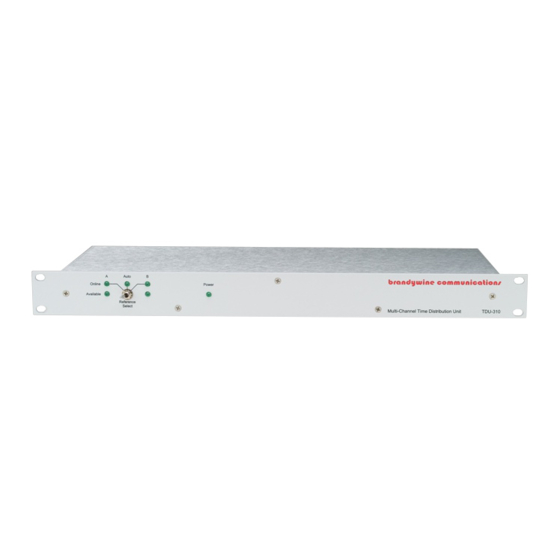
Page 18: Front Panel
Front Panel Rear Panel MANUAL P/N 900000019 REV G... -
Page 19: Outline Drawing
Figure 6.3 Outline Drawing MANUAL P/N 900000019 REV G... -
Page 20: Link Location
Figure 6.4 - Link Locations Note: “Std.” labels of LK1 to LK4 of 003000285 RevD (or older) were opposite than they’re shown. MANUAL P/N 900000019 REV G...
Need help?
Do you have a question about the TDU-310 and is the answer not in the manual?
Questions and answers