Advertisement
Quick Links
P DS - 60 c a 7 . 5 V
P DS - 60 c a 1 2 V
P DS - 60 c a 2 4 V
I N S T A L L A T I O N
G U I D E
PREPROGRAMMED CONTROL
Color Kinetics Incorporated
10 Milk Street, Suite 1100
Boston, MA 02108
Tel 888 Full RGB
Tel 617 423 9999
Fax 617 423 9998
info@colorkinetics.com
www.colorkinetics.com
ITEM# 109-000015-00 (7.5V)
109-000016-00 (24V)
109-000020-00 (12V)
This product is protected by one or more of the following patents: U.S. Patent Nos.
6,016,038, 6,150,774 and other patents listed at http://colorkinetics.com/patents/.
Other patents pending.
©2003-2005 Color Kinetics Incorporated. All rights reserved. Chromacore, Chromasic,
Color Kinetics, the Color Kinetics logo, ColorBlast, ColorBlaze, ColorBurst, ColorCast,
ColorPlay, ColorScape, Direct Light, iColor, iColor Cove, iPlayer, Optibin, QuickPlay,
Sauce, the Sauce logo, and Smartjuice are registered trademarks and DIMand,
IntelliWhite, Powercore, and Video With Light are trademarks of Color Kinetics
Incorporated.
PUB-000099-01 Rev 05
GETTING STARTED
Color Kinetics ® PDS-60ca 7.5V, PDS-60 12V and PDS-60ca 24V are
compact, robust power/data supplies for indoor and outdoor installa-
tions. The PDS-60ca 7.5V, PDS-60ca 12V, and PDS-60ca 24V provide
power and data to Color Kinetics Chromasic™ driven product lines,
and are available with DMX, Ethernet, and preprogrammed control
options.
This guide contains important information on installing and using your
new PDS-60ca. Please read it carefully and save it for future refer-
ence.
Included In This Box
• Power/data supply with cover, gasket attaching screws, and NPT
threaded seal plugs
• 2 Spare fuses (Only with PDS-60ca 7.5V and PDS-60ca 12V)
• Installation Guide
Additional Items Needed
• Mounting hardware and tools
• Standard strain relief cable clamps (Indoor applications)
• Water-tight conduit and fittings (As required per local codes)
• Electronic grade RTV Silicone (UL recognized) to seal conduit
connections as required
• 5/16" hex wrench or adjustable wrench for seal plugs
• Wire nuts
Scope of This User Guide
The goal of this user guide is to explain in an easily understandable
language the necessary steps to install the PDS-60ca with preprogrammed
control and assure peak performance. Its intended use is for reference
only, by persons who are fully qualified. This document should never be
considered a substitute for any provisions of a regulation or state and/or
local code.
Identification and Warnings of Safety Hazards
In accordance with ANSI Z535.4 the following system of identifying
the severity of the hazards associated with the products is used:
"
" Imminently hazardous situation which, if not avoided, will
DANGER
result in death or serious injury.
"
" Potentially hazardous situation that, if not avoided, could
WARNING
result in death or serious injury.
"
" Potentially hazardous situation that, if not avoided, may
CAUTION
result in minor or moderate injury or property damage.
: Ensure that main power supply is off before installing, wir-
DANGER
ing, or servicing the PDS-60ca power supply. Failure to adhere to
these instructions will result in death or serious injury.
: The PDS-60ca power supply must be installed by
WARNING
a
qualified professional in accordance with NEC and relevant
local codes. Failure to comply can result in death, serious injury, or
property damage.
: Do not attempt to install or use the PDS-60ca until you read
WARNING
and understand the installation instructions and safety labels. Failure
to adhere to these instructions could result in serious injury or property
damage.
: Do not use the PDS-60ca if power cables are damaged.
WARNING
Doing so can result in death, serious injury, and property damage.
: This is a class A product. In a domestic environment this
WARNING
product may cause radio interference in which case the user may be
required to take adequate measures.
: Ensure that the PDS-60ca is securely attached, properly
CAUTION
mounted, and free of excessive vibration. Failure to do so will result in
property damage and void the warranty.
: When sealing the PDS-60ca, ensure that the gasket is
CAUTION
seated properly, that no wires are pinched, and that the housing is
free of foreign material and debris. Failure to do so will cause seal
failure resulting in property damage and voiding the warranty.
: Do not hot swap. Ensure the power supply is off before con-
CAUTION
necting or disconnecting fixtures. Hot swapping will result in property
damage and void the warranty.
: Do not modify or alter the PDS-60ca. Doing so will void the
CAUTION
warranty.
: For outdoor installations, seal on points of entry and exit
CAUTION
with electronic grade RTV Silicone. Failure to do so will result in prop-
erty damage and void the warranty.
: The instructions and precautions set forth in this user guide are
NOTE
not necessarily all inclusive, all conceivable, or relevant to all applica-
tions as Color Kinetics cannot anticipate all conceivable or unique
situations.
Owner/User Responsibilities
It is the responsibility of the contractor, installer, purchaser, owner, and
user to install, maintain, and operate the PDS-60ca in such a manner
as to comply with all state and local laws, ordinances, regulations,
and the American National Standard Institute Safety Code.
INSTALLING THE PDS-60ca
The PDS-60ca shall be installed by a qualified electrician in accor-
dance with NEC and relevant local codes for power supplies. A
power screwdriver is recommended for mounting the unit.
: Ensure proper installation for outdoor applications to main-
CAUTION
tain NEMA 4 ratings. Failure to do so will result in property damage
and void the warranty.
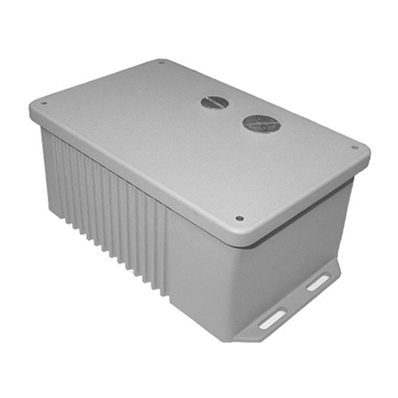
Mounting the Housing
• Select the location to mount the housing, keeping the PDS-60ca
within the maximum distance specified for your fixture. Refer to your
fixture user guide for the cable run information.
: PDS-60ca must be installed in a location that allows air to
CAUTION
move freely. Packing insulation around the housing or mounting in a
sealed location that raises ambient temperature above 104º F (40º C)
will result in property damage and void the warranty.
• Using the seal plugs and gaskets provided, seal all conduit holes
not needed for the installation. Tighten plugs until gaskets are
slightly compressed. Do not over tighten.
• Mount the housing to a flat surface using four screws suitable for the
mounting surface. Mounting slots are located on the flanges at each
end of the housing. (See mounting details, Fig. 1.)
8.3"
Fig. 1
(21 cm)
2"
(5 cm)
Power Out/
Data
Connection
WIRING THE PDS-60ca
After mounting the power/data module, you are ready to connect
power, lights, and data to the PDS-60ca.
Connecting Power to the PDS-60ca
: Turn off main power supply before wiring the PDS-60ca.
DANGER
Failure to do so will result in death or serious injury.
Indoor Installation
• Insert power cable into the power connection chamber of the PDS-
60ca.
• Using pig tails and wire nuts, connect Line (black), Neutral (white),
and Ground (green/yellow). Follow local electrical codes for
internal wire bending.
• Use a standard strain relief to hold the cable. See Fig. 2
• Use a standard strain relief to hold the cable. See Fig. 2
Fig. 2
Ground from external
Ground from
power source.
internal
power supply
Line - Black
Neutral - White
Ground - Green/Yellow
100-240VAC
Strain Relief
Outdoor Installation
• Pull power cable through outdoor rated conduit and into the
power connection chamber of the PDS-60ca. Use RTV Silicone
on the conduit coupler and ensure that conduit connection to the
PDS-60ca is water-tight.
• Using wire nuts, connect Line (black), Neutral (white), and Ground
(green/yellow). Follow local electrical codes for internal wire
bending. See Fig. 3.
Fig. 3
It is the end user's responsibility to use the proper conduc-
NOTE :
tors to permanently connect the incoming facility power, and to
provide means for disconnecting the system.
Connecting Lights to the PDS-60ca
• Insert the fixture leader cable into the power out/data connection
chamber of the PDS-60ca.
: Outdoor rated lights have water-tight couplers on the cables.
NOTE
Ensure that the water-tight coupling is properly installed and sealed
with RTV Silicone to ensure NEMA 4 protection. Refer to the user
guide for your lights for instructions. These couplers also provide
Mounting Slots
Mounting Slots
strain relief. See. Fig. 4
• Plug connector into a power output receptacle. Power outputs are
1"
(2.5)
labeled Out 1 and Out 2. See Fig. 4
• For indoor rated lights, use a standard screw connector strain relief
to hold the cable. See Fig. 4
0.8"
• Refer to the user guide for your lights to determine maximum
(2 cm)
number of lights per power/data supply and specific wiring
requirements.
Fig. 4
INDOOR
OUT 1
OUT 2
Strain
Relief
OUTDOOR
OUT 1
OUT 2
O-Ring
Line - Black
Neutral - White
Ground - Green
100-240VAC
Conduit with
water-tight
fitting
Leader
Cable
Assembled Coupler
Seal with RTV
Silicone.
Grommet
Locknut with
Internal Gland
Advertisement

Related Manuals for Color Kinetics PDS-60CA

Summary of Contents for Color Kinetics PDS-60CA
- Page 1 : Outdoor rated lights have water-tight couplers on the cables. NOTE 6,016,038, 6,150,774 and other patents listed at http://colorkinetics.com/patents/. : Do not attempt to install or use the PDS-60ca until you read WARNING Ensure that the water-tight coupling is properly installed and sealed Other patents pending.
- Page 2 Flex SL, iColor Flex SLX, iColor Cove EC, POSITION Each power output terminal of the PDS-60ca 7.5V and PDS-60ca 12V iColor Cove QL or Pro products. is equipped with a fuse. Red LEDs are located next to each fuse to for iColor Tile FX.