Advertisement
Quick Links
KMP3/KMP4
Connecting cable
Assembly instructions
8116204
2020-06a
[8116206]
Translation of the original instructions
© 2020 all rights reserved to Festo SE & Co. KG
1
Applicable documents
All available documents for the product è www.festo.com/sp.
2
Safety
2.1
Safety Instructions
–
Do not connect or disconnect plug connector when powered.
–
Only mount the product on components that are in a condition to be safely
operated.
–
Assembly and installation should only be carried out by qualified personnel.
These personnel have electrical training or a relevant qualification.
2.2
Intended use
Connection of a CPV valve terminal to a higher-order controller.
3
Configuration
3.1
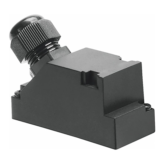
Product design
Fig. 1 KMP3/KMP4-9P...
Fig. 2 KMP3-25P...
Fig. 3 KMP4-25P...
Festo SE & Co. KG
Ruiter Straße 82
73734 Esslingen
Germany
+49 711 347-0
www.festo.com
8116204
1 Sub-D socket
2 Wire end (10x)
3 Cable
4 Screw (2x)
1 Sub-D socket
2 Wire end (18x)
3 Cable
4 Screw (2x)
1 Sub-D socket
2 Wire end (25x)
3 Cable
4 Screw (2x)
3.2
Contact assignment
Electrical connection 1
Field device side
1 Socket
Pin
KMP3/KMP4-
KMP3-25P...
KMP4-25P...
9P...
1
1
1
2
2
2
3
3
3
4
4
4
5
5
5
6
6
6
7
7
7
8
8
8
–
9
9
–
10
10
–
11
11
–
12
12
–
13
13
–
14
14
–
15
15
–
16
16
–
n.c.
17
–
n.c.
18
–
n.c.
19
–
n.c.
20
–
n.c.
21
–
n.c.
22
–
n.c.
23
–
24
24
9
25
25
1) Colour code in accordance with IEC 60757:1983-01
Tab. 1 Contact assignment
4
Assembly
4.1
Mounting of Electrical Connection 1
1. Align socket 1 to match plug.
2. Connect socket 1 to the plug.
3. Tighten screws 4. Tightening torque: 0.6 Nm ± 20 %
4.2
Mounting of Electrical Connection 2
1. Shorten and pre-assemble cable sheath and wire ends as needed.
2. Connect the wires in accordance with the contact assignment.
4.3
Strain Relief
Strain Relief for Movable Wiring
•
Fix the cable sheath in the area of the wire ends 2.
Ä No force may be transferred to the cables.
4.4
Change of cable outlet direction (optional)
Fig. 4
1. Remove two screws [A] from the contact holder [B].
2. Carefully pull contact holder [B] from the cable socket.
Electrical connection 2
Controller side
2 Wire ends
Wire colour
1)
WH
GN
YE
GY
PK
BU
RD
VT
GYPK
RDBU
GNWH
BNGN
YEWH
BNYE
GYWH
BNGY
WHPK
BNPK
BUWH
BNBU
RDWH
BNRD
BKWH
BN
BK
Advertisement

Related Manuals for Festo KMP3 Series


Summary of Contents for Festo KMP3 Series
- Page 1 Assembly instructions 8116204 2020-06a [8116206] 8116204 – GYPK – RDBU Translation of the original instructions – GNWH © 2020 all rights reserved to Festo SE & Co. KG – BNGN – YEWH – BNYE Applicable documents – GYWH – BNGY All available documents for the product è www.festo.com/sp.
- Page 2 7. Mount the energy chain è corresponding instructions. 8. Fasten cables: – with short energy chains (length < 1 m) at both ends of the chain – with long sliding energy chains (length > 1 m) only at the driver end Fig. 9 9. Do not move cables all the way to the fastening point. Ä...