Table of Contents
Advertisement
Quick Links
Advertisement
Table of Contents

Subscribe to Our Youtube Channel
Related Manuals for Nokeval FT20


Summary of Contents for Nokeval FT20
- Page 1 Nokeval FT20 User Manual...
-
Page 2: Table Of Contents
Firmware settings .............................. 9 Operation................................. 14 SCL protocol ..............................15 Modbus protocol ............................. 16 Nopsa commands ............................19 Specifications ..............................23 Document information Device Scope: FT20 Device Versions: 1.1 to 1.2 Document Type: manual Document ID: 2873 Document Version: Document Date:... -
Page 3: Introduction
FT20 receives and buffers the data packets that wireless transmitters have sent. It can also relay the data packets so that large areas can be covered using only one receiver. It automatically recognizes the types of the transmitters, so different kinds of transmitters can be used simultaneously. -
Page 4: Installing
Installing Mounting The best installation environment for a radio receiver is above a big grounded horizontal metal surface surrounded by as few as possible vertical metal surfaces. Antenna is to be installed perpendicular to the metal surface. The best range for the transmitter is achieved when there is a line-of-sight from the receiver to the transmitter. - Page 5 Using two repeaters The picture below shows how two repeaters can be daisy chained. Warehouse Repeater Repeater Receiver 50..200 m Coverage area RS-485 The downside of daisy chaining is that now both repeaters relay also the data that they receive from the other repeater.
- Page 6 The maximum number of radio transmitters in a coverage area is limited by radio standards. The use of repeaters reduces the maximum number of transmitters because repeaters use the same frequency channel as transmitters. The following example table shows the allowed maximum number of Nokeval radio transmitters in a coverage area.
- Page 7 Default RS485 settings RS485 AC term. FT20 serial module has a 4-pin terminal block for power supply and RS-485 connection. Serial module features also a round 3.5 mm POL programming connector jack found on many other Nokeval products as well. FT20 radio module contains BNC type antenna connector.
-
Page 8: Maintenance
Jumpers FT20 has three jumpers in the serial module: ”RS485 AC term” RS-485 termination jumper, default serial settings jumper and jumper which turns repeater on or off (if enabled in firmware settings). -
Page 9: Firmware Settings
Mekuwin MekuWin can be used to change settings on various Nokeval products. It has a unique feature: it loads the structure and the contents of the configuration menu from the target device, so the same MekuWin version can be used with past and forthcoming products. There is no need to update this software every time a new product or product version is released. - Page 10 Configuration settings The configuration settings are arranged as a hierarchical tree: The Conf menu has submenus, and these contain settings and possibly more submenus, etc. Menu of the FT20: Serial Protocol Baud rate Bits Conf Serial Address Channels Channels Timeout[min]...
- Page 11 Channels submenu Up to 100 channels can be set up in the radio receiver. These channels can be set up to contain any data received from the radio transmitters. The values of these channels can then be queried over the serial interface.
- Page 13 Repeater submenu Repeater • Off: Repeater function is off. • Repeater On: Repeater function is on. • Repeater Jumper: Jumper controls the repeater function. Default setting. ID filter ID filter Extra bytes If checked, only those IDs that are checked in Channels/ChX/Repeater Max jumps submenu will be repeated.
-
Page 14: Operation
Operation FT20 has one diagnostic LED that shines through the case of the device. This LED blinks slowly when the unit is operational but not receiving any radio data packets at the moment, and blinks rapidly when radio data packets are being received. -
Page 15: Scl Protocol
SCL protocol A full specification of the Nokeval SCL protocol can be downloaded from Nokeval WWW site. In short, the command frame consists of an address byte (bus address+128), a human-readable command, an ETX character (ASCII 3) and an XOR checksum of all bytes excluding the address byte. A normal response consists of an ACK (ASCII 6), a human-readable response, an ETX and an XOR checksum of all the bytes including the ACK. -
Page 16: Modbus Protocol
• 110 Nopsa: This is used to transport Nopsa protocol on Modbus. Command 17 returns 0x11 <byte count> 0x00 0xFF, followed by for example “FT20 V1.0 A123456” Maximum Modbus packet length is 240 bytes. This affects the maximum possible register count that can be accessed simultaneously with commands 3, 4 and 16. - Page 17 Input registers Table E1 0..1 Ch1\Reading FLOAT (LSW, MSB) Signed 2..3 Ch2\Reading FLOAT (LSW, MSB) Signed Value Type … … MTR260 198..199 Ch100\Reading FLOAT (LSW, MSB) Signed MTR262 MTR264 200..201 Ch1\Reading FLOAT (MSW, MSB) Signed MTR265 202..203 Ch2\Reading FLOAT (MSW, MSB) Signed MTR165 …...
- Page 18 Holding registers Address Name Type Values 2000 Conf\Serial\Protocol ENUM See table E3 2001 Conf\Serial\Baud rate ENUM See table E4 2002 Conf\Serial\Bits ENUM See table E5 2003 Conf\Serial\Address BYTE Unsigned 0...247 2004 Conf\Channels\Timeout[min] BYTE Unsigned 1...255 2005 Conf\Channels\Count BYTE Unsigned 0...100 2006 Conf\Channels\Ch1\ID WORD...
-
Page 19: Nopsa Commands
Nopsa needs some transfer layer protocol, which takes care of addresses, transfer error management and packet length. This device supports Nopsa commands over either Nokeval SCL or Modbus RTU protocols. Supported Nopsa commands •... - Page 20 Transport protocol SCL When Nopsa packets are transported on SCL data is converted to hexadecimal notation (0-9 and A-F). One Nopsa byte will become 2 bytes. No spaces between characters. Packet starts with SCL command N and a space. ’N’ ’ ’ Nopsa-packet in hexadecimal ETX BCC Response is transferred also same way in hexadecimal, but N command is not appended.
- Page 21 Nopsa command group 1 – Basic commands Command Response 1/0 (Type) 0x01 | 0x00 status | string string: Device type as string -> FT20 Command Response 1/1 (Version) 0x01 | 0x01 status | string string: Device version as string -> V1.0...
- Page 22 Nopsa command group 4 – Logger commands Real-time data buffer commands Command Response 4/0 (Buffer info) 0x04 | 0x00 status | size*2 | write position*2 size: Ring buffer size (96), write position: position next to be written Command Response 4/1 (Find oldest) 0x04 | 0x01 status | read position*2 | lap counter read position: position where is oldest data,...
-
Page 23: Specifications
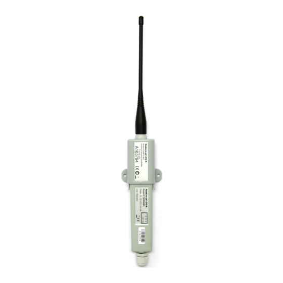
-40…+70 °C terminal 4 D0. Humidity max 90 %RH non-condensing Maximum cable length is Protection class IP66 1000 m Protocol Nokeval SCL, Modbus RTU, Dimensions Nopsa Length 379.6 mm, inc. antenna Baud rates 300, 600, 1200, 2400, 4800, Width 60.2 mm...
Need help?
Do you have a question about the FT20 and is the answer not in the manual?
Questions and answers