Table of Contents
Advertisement
Quick Links
SAFETYTEST 3N Manual
SAFETYTEST 3N Manual
Texts and drawings were prepared with great care. However, errors can still be present. The
manufacturer assumes no direct or indirect liability for any damages which may occur.
Please read this manual carefully before using the leakage current clamp.
Warning markings in the manual and on the clamp are meant to warn of risks or dangers.
General warning see manual
This warning marking in the manual is intended to warn of risks or
dangers of intended or not intended use
Disregarding these warnings may result in serious injuries or death.
Warning when exchanging fuses
Warning of the risk of fire, e. g. when using improper fuses.
SAFETYTEST GmbH
Picture 1
16 April 2006
TEST
SAFETY
Page 1 of 18
Advertisement
Table of Contents

Related Manuals for Safetytest 3N


Summary of Contents for Safetytest 3N
- Page 1 TEST SAFETYTEST 3N Manual SAFETY SAFETYTEST 3N Manual Picture 1 Texts and drawings were prepared with great care. However, errors can still be present. The manufacturer assumes no direct or indirect liability for any damages which may occur. Please read this manual carefully before using the leakage current clamp.
-
Page 2: Table Of Contents
TEST SAFETYTEST 3N Manual SAFETY Contents General Warnings ....................4 Application ......................5 Scope of Delivery ....................5 3.1 Standard: ........................5 3.2 Accessories (Optional): ..................... 5 3.3 Spare parts: ....................... 5 3.4 Software (Optional): ....................5 Connections and user interface ................6 4.1 Connections (Picture 2) ..................... - Page 3 TEST SAFETYTEST 3N Manual SAFETY Testing Electrical Appliances ................11 10.1 Qualification ......................12 10.2 Mains connection ......................12 10.3 Visual inspection .......................12 10.4 Measurements ......................13 10.5 Functional test ......................13 10.6 Checking the markings .....................13 10.7 Documentation of the test ..................13 Connections, Examples ..................14 Updating the Firmware ..................15...
-
Page 4: General Warnings
TEST SAFETYTEST 3N Manual SAFETY 1 General Warnings The tester “Safetytest 3N“complies to the following safety standards: EN 61010-1 SAFETY REQUIREMENTS FOR ELECTRICAL EQUIPMENT FOR MEASUREMENT, CONTROL, AND LABORATORY USE DIN VDE 0404 parts 1 and 2, In order to warrant the safe application of the tester the following warnings have to be... -
Page 5: Application
NOTE! When connecting the appliance to mains hazardous voltages may occur on conductive parts which are not connected to PE. 2 Application The tester “SAFETYTEST 3N“ is used for testing the electrical safety of appliances. 3 Scope of Delivery Standard:... -
Page 6: Connections And User Interface
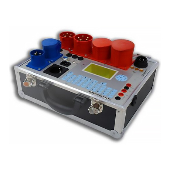
TEST SAFETYTEST 3N Manual SAFETY 4 Connections and user interface Picture 2 1. 32 A CEE three phase plug for connection power 2. 32 A CEE three phase test socket 3. 16 A CEE three phase test socket 4. 16 A CEE AC test socket 5. -
Page 7: Connections (Picture 2)
TEST SAFETYTEST 3N Manual SAFETY 23. Phase fuses L1, L2, L3 for the 16A test sockets (use only replacement fuses supplied by the manufacturer, since there exists danger of fire.) 24. Fuse FF 250mA for the earth bond test. Connections (Picture 2) Before connection the tester to mains the appropriate warnings in chapter 2 have to be observed, as well as the warnings for the connecting leads and accessories attached. -
Page 8: Fuses F1, F2 And F3 For All 16A Testing Sockets (Picture 2/23)
TEST SAFETYTEST 3N Manual SAFETY Fuses F1, F2 and F3 for all 16A testing sockets (picture 2/23) The 16 A testing sockets are fused by three fuses(6x32 16 AT) F1, F2 and F3 for phases L1, L2 and L3. Keyboard The alphanumeric keyboard with the menu keys is used to operate the easy to use user menu system. -
Page 9: Functional Description
TEST SAFETYTEST 3N Manual SAFETY Key ”Shift“ Function: Switch between capital and small letters Key ”Space“ Function: Space character Alphanumeric keys. When entering ID numbers the numerical function is pre selected. For all other entries the alphabetical entry is pre selected. -
Page 10: Testing The Mains Connection
TEST SAFETYTEST 3N Manual SAFETY 6 Testing the Mains Connection The person responsible for the electrical installation is responsible for the safety of the power system to which the tester is connected. The test of the installation is not part of the appliance test. Nevertheless the tester allows a Note: This is not a complete test as required by IEC 16557. -
Page 11: Three Phase Connection
TEST SAFETYTEST 3N Manual SAFETY In the configuration “Advanced” it is possible to perform measurements in spite of the incorrect polarity. NOTE!!! If the polarity is incorrect, the mains voltages are displayed incorrectly. If the polarity is correct, the display indicates “AC” and “PE<30V”. -
Page 12: Qualification
TEST SAFETYTEST 3N Manual SAFETY For class II appliances and for isolated all conductive parts on class I appliances test of the touch leakage current. Functional test Notes: Before performing a leakage test on class I appliances the earth bond test has to be passed. -
Page 13: Measurements
TEST SAFETYTEST 3N Manual SAFETY 10.4 Measurements See Menu system 10.5 Functional test After performing the electrical test a functional test is required. 10.6 Checking the markings The presence of required markings must be checked and if necessary renewed. 10.7 Documentation of the test The passed test has to be documented. -
Page 14: Connections, Examples
TEST SAFETYTEST 3N Manual SAFETY 11 Connections, Examples Earth bond test: Use the probe to test all conductive parts connected to PE SAFETYTEST GmbH 16 April 2006 Page 14 of 18... -
Page 15: Updating The Firmware
TEST SAFETYTEST 3N Manual SAFETY Testing conductive parts not connected to PE: Use the probe to test these parts. If there are rotating or moving parts test these in motion. The best way is to use the optional brass brush probe. Use protective glasses. -
Page 16: Error Messages, Removing Faults
TEST SAFETYTEST 3N Manual SAFETY Start the PC-program Bootloader.exe Setup the baud rate to19200Bd Set the Com port. Set the com port and the baud rate. If in doubt of the com port go to WINDOWS device manager/system/hardware and check the hardware configuration Open File, „Open Hex File“... -
Page 17: Leakage Current Measurement Shows "F" As A Result
TEST SAFETYTEST 3N Manual SAFETY Perform an insulation resistance measurement between the appliance mains plug and the accessible conductive parts not connected to PE. All switches of the appliance must be closed. If there is a circuit breaker inside it must be bridged. -
Page 18: Disposal
TEST SAFETYTEST 3N Manual SAFETY Interface: RS232. USB via adapter. Can be remotely controlled. Memory, Real time clock: approx. 1000 measurement sequences with time and date. 16 Disposal The disposal of a decommissioned tester must be carried out by the customer according to the national regulations.
Need help?
Do you have a question about the 3N and is the answer not in the manual?
Questions and answers