
Related Manuals for Safetytest 1ST


Summary of Contents for Safetytest 1ST
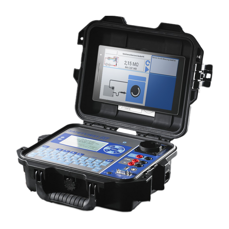
- Page 1 TEST SAFETYTEST 1ST User Manual SAFETY SAFETYTEST 1ST User Manual Figure 1 SAFETYTEST GmbH June 15 2015 Page 1 of 22...
- Page 2 TEST SAFETYTEST 1ST User Manual SAFETY Texts, drawings and technical information were prepared with great care. However, errors may still be present. The author and the manufacturer assume no direct or indirect liability for any incorrect or incomplete descriptions or any damages that may occur.
-
Page 3: Table Of Contents
TEST SAFETYTEST 1ST User Manual SAFETY Table of Contents General Safety and Warning Notes ...............5 Application ......................6 Scope of Delivery and Accessories ..............6 3.1 Scope of Delivery (Standard): ..................6 3.2 Accessories (optional): ....................6 3.3 Software (Optional): ....................6 Connections, Display and Keyboard ..............7 4.1 Connections (Figure 2) ....................8... - Page 4 TEST SAFETYTEST 1ST User Manual SAFETY Updating the Firmware ..................20 Error messages, Removing Faults ..............21 13.1 The display remains dark ..................21 13.2 Touch current display is 0,000 mA ................21 13.3 Contact current measurement larger than 0,5 mA ............. 21 13.4 Leakage current measurement shows “F“...
-
Page 5: General Safety And Warning Notes
SAFETYTEST 1ST User Manual SAFETY 1 General Safety and Warning Notes The tester “Safetytest 1ST” was built and complies with the following safety standards. DIN EN 61010-1 (VDE 0411 part 1), SAFETY REQUIREMENTS FOR ELECTRICAL EQUIPMENT FOR MEASUREMENT, CONTROL, AND LABORATORY USE DIN VDE 0404 parts 1 and 2, “Geräte zum Prüfen, Messen oder Überwachen von Schutzmaßnahmen“... -
Page 6: Application
PE. 2 Application The tester “SAFETYTEST 1ST” is used for testing the electrical safety of appliances. 3 Scope of Delivery and Accessories Scope of Delivery (Standard): •... -
Page 7: Connections, Display And Keyboard
TEST SAFETYTEST 1ST User Manual SAFETY 4 Connections, Display and Keyboard Figure 2 1. OK LED indicates a PASSED test result 2. FULT LED 3. Panel for individual measurements 4. Glow lamp indicating that mains is connected to the test socket 5. -
Page 8: Connections (Figure 2)
TEST SAFETYTEST 1ST User Manual SAFETY Connections (Figure 2) Before connecting the tester to the mains, the appropriate warnings in chapter 1 have to be observed, as well as the warnings for connecting the leads and accessories attached. It is safe to use the instrument for its intended use only. The testing of the rotective conductor potential takes place through using the fingercontact after the tester is connected. -
Page 9: Display (Figure 2/5)
The baud rate to the PC is 19200 baud. The interface is galvanically isolated. The firmware of the “SAFETYTEST 1ST” may be updated easily via the USB/COM interface. An update allows you to get the latest testing sequences and change the display language, The optional barcode scanner or the transponder scanner used for scanning ID numbers from the UUTs may be connected to the RS232 interface. -
Page 10: Connection Test
TEST SAFETYTEST 1ST User Manual SAFETY Note: • Through touching the the fingercontact, it is possible to deteremine whether the protective conductor is connected. This is not the case, if after touching the fingercontact the red LED lights up. •... -
Page 11: Ac Connection
The display allows a comfortable menu based testing sequence, shows all measuring functions, limits and values. The menu structure is documented in a separate document “SAFETYTEST 1ST-Menu Structure”. It is kept up to date together with the software. 9 Taking the Tester into Operation Visual check •... -
Page 12: Qualification
TEST SAFETYTEST 1ST User Manual SAFETY Before performing a leakage current test on class II or III (except for IT appliances) an insulation resistance test of 500 V DC has to be passed. Accessible connections and generated SELV voltages have to be checked according to the SELV specifications. -
Page 13: Measurements
TEST SAFETYTEST 1ST User Manual SAFETY 10.4 Measurements See menu system 10.5 Functional Test After performing the electrical test a functional test is required. A short test may be sufficient. 10.6 Checking the Markings The presence of safety required markings must be checked and if necessary renewed or completed. -
Page 14: Connections, Pictures, Examples
TEST SAFETYTEST 1ST User Manual SAFETY 11 Connections, Pictures, Examples 11.1 Earth bond test of AC appliances Protective conductor: Use the protective conductor probe to scan the housing parts and move the connection cord. 11.2 Earth bond test of three phase equipment using a test lead Earth bond test: Use the probe to test all conductive parts connected to PE. -
Page 15: Earth Bond Test Of Three Phase Equipment Using The Extension Lead Adapter
TEST SAFETYTEST 1ST User Manual SAFETY 11.3 Earth bond test of three phase equipment using the extension lead adapter Testing sequence: „Cl with Clamp“. Connect the test lead to the yellow connection on the tester and the large earth pin on the CEE connector. Probe all earthed parts of the appliance under test. -
Page 16: Insulation Resistance Test Ln-Pe
TEST SAFETYTEST 1ST User Manual SAFETY Insulation resistance test LN-PE, Substitute leakage test: Connect appliance to test socket. Switch on the appliance. The test is done without applying mains. 11.6 Insulation resistance test LN-PE of three phase equipment using the extension lead adapter 11.7... -
Page 17: Extension Lead Test
TEST SAFETYTEST 1ST User Manual SAFETY 11.9 Extension lead test Connect the adapter to a CEE socket of the installation. Connect the appliance to the socket of the adapter. Use the current clamp to encompass L1, L2, L3 and N without PE Connect the current clamp to the tester. - Page 18 TEST SAFETYTEST 1ST User Manual SAFETY During the PRCD-S test, the Schuko plug is inserted into the test socket of the tester. The other side of the extension cord is inserted into the panel plug on the right-hand side of the tester or an adapter as shown in the figure above.
-
Page 19: Testing Welding Appliances
TEST SAFETYTEST 1ST User Manual SAFETY 11.11 Testing Welding appliances During the testing of welding equipment, both electrodes, as shown in the figure, are attached to the tester. The power cord of the welding quipment is attached to the power socket of the tester. - Page 20 TEST SAFETYTEST 1ST User Manual SAFETY 12 Updating the Firmware Connect the tester to the USB interface of the PC. Start the PC program Bootloader. Select the COM port in the menu Select the menu „Open Hex File“ Disconnect the power plug from the tester.
- Page 21 TEST SAFETYTEST 1ST User Manual SAFETY 13 Error messages, Removing Faults 13.1 The display remains dark Note: Possibly there is no N connection on the mains socket. Possibly one of the fuses of the tester has blown. 13.2 Touch current display is 0,000 mA This is no error but the safe condition.
- Page 22 The disposal of a decommissioned tester must be carried out by the customer according to the national regulations. 17 Guarantee The tester “SAFETYTEST 1ST” is subject to a strict quality assurance system. A calibration certificate with the documentation of the test results is delivered together with the tester.
Need help?
Do you have a question about the 1ST and is the answer not in the manual?
Questions and answers