
Related Manuals for AVANT A424013

Summary of Contents for AVANT A424013
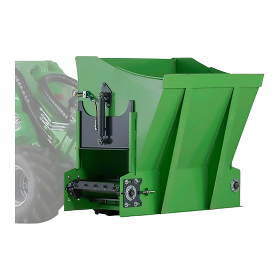
- Page 1 English Silage dispenser 2020 1 Operator's Manual for Attachment Silage dispenser Product number A424013 www.avanttecno.com A431965 2020 1 EN 2018-...
- Page 2 Silage dispenser 2020 1...
-
Page 3: Table Of Contents
Silage dispenser 2020 1 CONTENTS 1. FOREWORD ............................4 Warning symbols used in this manual ........................... 5 2. DESIGNED PURPOSE OF USE......................6 3. SAFETY INSTRUCTIONS FOR USING THE ATTACHMENT ............7 Personal protective equipment ..........................10 Safe shutdown procedure ............................10 4. -
Page 4: Foreword
If you sell or transfer the equipment, be sure to hand over this manual to the new owner. If the manual is lost or damaged, you can request a new one from your Avant dealer or from the manufacturer. -
Page 5: Warning Symbols Used In This Manual
5 (36) Warning symbols used in this manual The following warning symbols are used throughout this manual. They indicate factors that must be taken into account to reduce the risk of personal injury or damage to property: WARNING SAFETY ALERT SYMBOL This symbol means: “Warning, be alert! Your safety is involved!”... -
Page 6: Designed Purpose Of Use
2. Designed purpose of use The AVANT Silage dispenser is an attachment that is suitable for use with AVANT multi purpose loaders that are shown in Table 1. The attachment is intended for dispensing precision chopped silage and feeding stuffs made with feed mixers. -
Page 7: Safety Instructions For Using The Attachment
7 (36) 3. Safety instructions for using the attachment Please bear in mind that safety is the result of several factors. The loader-attachment combination is highly powerful and improper or careless use or maintenance may cause serious personal injury or property damage. - Page 8 8 (36) Make sure that overhead clearance is sufficient. Hitting an overhead obstacle may cause the loader to tip over. Keep a safe distance from electric cables, lamps, or other electric systems; hitting live parts may cause electric shock. ...
- Page 9 WARNING parts. Use only to dispense materials that are commonly used as feeding materials. Consult your Avant dealer if necessary. Choking hazard - Ensure ventilation when using a loader with combustion engine indoors. Using the loader engine indoors increases, among other things, the carbon dioxide level of the air, which affects the safety of the operator.
-
Page 10: Personal Protective Equipment
10 (36) 3.1 Personal protective equipment Remember to wear proper personal protective equipment: The noise level at the driver's seat may exceed 85 dB(A) depending on loader model and operating cycle. Extended exposure to loud noise can cause hearing impairment. Wear hearing protection while working with the loader. ... -
Page 11: Technical Specifications
330 kg Recommended input of hydraulic flow: 30-40 l/min, 22,5 MPa (225 bar) Maximum input of hydraulic energy: 60 l/min, 22,5 MPa (225 bar) Suitable Avant loaders: See Table 1 Options Hydraulic side hatch operation A429734 Weight of the side hatch ~10 kg 4.1 Safety labels and main components of the attachment... - Page 12 Attachment identification plate Do not use the lifting points when there is material within the bucket. Table 4 - Silage dispenser - Main components Frame with Avant quick attach brackets Discharge conveyor Hydraulic motor of discharge conveyor Conveyor tension adjustment...
-
Page 13: Assembling The Attachment
Do not stay in the area between the attachment and the loader. Mount the attachment only on level surface. WARNING Never move or lift an attachment that has not been locked. Avant quick coupling system: Step 1: Lift the quick attach plate locking pins up and turn them backwards into the slot so that they are locked in the upper position. -
Page 14: Connecting And Disconnecting Hydraulic Hoses
5.1 Connecting and disconnecting hydraulic hoses On Avant loaders the hydraulic hoses are connected using the multi connector system. If you have an Avant 300-700 series loader with the conventional quick couplers and wish to change to the multi connector system, contact your Avant dealer or service point for instructions or installation services. - Page 15 15 (36) Keep all fittings as clean as possible; use the protective caps on both the attachment and the loader. Dirt, ice, etc. may make using the fittings significantly more difficult. Never leave the hoses hanging on the ground; place the couplings onto the holder on the attachment.
-
Page 16: Electric Connection
16 (36) 5.2 Electric connection Electric functions of the attachment: As standard, the Silage dispenser is equipped with a manual side hatch adjustment. The hydraulic side hatch operation is available as an option. The hydraulic side hatch operation can be controlled with the standard electric harness that is supplied with the attachment, with the Opticontrol®... - Page 17 17 (36) If your loader is equipped with the Opticontrol ®, the Attachment control switch pack, and the loader is manufactured after 2016: electric socket integrated multiconnector, electric harness attachment is connected when the multiconnector is coupled. Clean both multiconnectors before connecting the multiconnector.
-
Page 18: Operating The Attachment
18 (36) 6. Operating the attachment Check the attachment and the operating environment once more before starting to work, and that all obstacles have been removed from the operating area. Quick inspection of the equipment and the operating area before use are parts of ensuring safety and the best performance of the equipment. -
Page 19: Checks Before Use
19 (36) Risk of tipping over - Avoid overload. Loader can tip over when handling too heavy loads, or because of dynamic movements caused by driving with and handling of a heavy WARNING load. Do not extend the telescopic boom when the load approaches the lifting capacity of the loader, or when the loader boom is in horizontal position. -
Page 20: Operator Qualification
20 (36) 6.2 Operator qualification Anyone who intends to use the attachment must: Know the intended use of the attachment. Know how to use the loader safely in different operating conditions. Read and always follow the instructions concerning the use of the attachment in this operator's ... - Page 21 21 (36) Risk of tipping over - Always keep silage dispenser close to the ground when WARNING filling it from a silo or other equipment. Added weight from silage can tip the loader over, causing injuries from impact and getting thrown out from the loader.
-
Page 22: Filling The Bucket
22 (36) 6.3.2 Filling the bucket Correct working method is important when lifting material from a pile, as lifting material from a pile requires the most power from the loader. Especially when using a bucket with a long base, the correct working method should be observed for the best performance of the equipment. -
Page 23: Operating The Silage Dispenser
23 (36) 6.4 Operating the Silage dispenser Keep the material being transported as close to the loader and as low as possible. Additional counterweights may be needed on the loader. See the operator's manual of the loader for the tipping load and the operating capacity of the loader. The dispenser is operated by moving the auxiliary hydraulics control lever of the loader (or by pressing buttons of the electric joystick, if equipped). -
Page 24: Adjusting Dispensing Rate
24 (36) 6.5 Adjusting dispensing rate The conveyor speed and material distribution rate are adjusted by the loader engine RPM. When silage is pushed out form the bucket, the adjustable hatch prevents too much of silage to be ejected at once. The hatch (1) is adjusted by repositioning the bracket (2) manually. -
Page 25: Hydraulic Side Hatch Operation (Optional Extra)
25 (36) 6.6 Hydraulic side hatch operation (Optional extra) 6.6.1 Safety instructions for hydraulic assemblies High-pressure ejection of fluid may penetrate skin and cause serious injuries: Risk high pressure fluid injection through skin - High-pressure ejection of fluid may penetrate skin and cause serious DANGER injuries. -
Page 26: Tightening Hydraulic Fittings
26 (36) 6.6.2 Tightening hydraulic fittings Tighten the fittings carefully according to given instructions and safety procedures. Keep in mind that over tightening will break a fitting. Tighten basic fittings carefully with hand tools using moderate torque. The elbow fittings should be tightened at last, after hoses have been fitted to their clamps. Allow the hydraulic systems of the loader and of the attachment to cool down completely before any work on hydraulic systems. -
Page 27: Installation
27 (36) Check the routing of hoses and movements of the attachment After tightening the hydraulic components, test the movements of the attachment thoroughly. Check that the hydraulic hoses cannot get stretched or pinched in any position of the loader boom or the attachment, and check that the hoses are not in contact with sharp edges. -
Page 28: Using The Hydraulic Side Hatches
28 (36) Connect the hydraulic fittings and hoses as shown in the adjacent figure. Connect the electric supply as instructed on page 6.6.4 Using the hydraulic side hatches The actual hatch operation is controlled with auxiliary hydraulics control lever. Select the desired hatch with hatch control valve manually. Select between hatch and conveyor function as instructed below. -
Page 29: Transport Position
29 (36) Alternatively, when the loader is equipped with the optional Opticontrol system, the attachment control ® switch pack can be used to control the hatch adjustment. See page 16 for instructions about how to connect the electric harness of the attachment. The selection between the hatch and conveyor function is controlled by switch number 1. - Page 30 30 (36) To ensure the stability of an uncoupled attachment, place it on a pallet as shown in the figure below: Risk crushing Uncoupled bucket may tip over. Ensure stability DANGER uncoupled attachment. Keep a safe distance during coupling. Ensure the stability by placing the attachment firmly on the ground to a stable position with its...
-
Page 31: Maintenance And Service
Finding any fault means that the hydraulic hose or component must be replaced and the equipment must not be used until it is repaired. Spare parts are available from your nearest AVANT retailer or authorised service point. Leave the repair work to professional service technicians, if you don’t have adequate knowledge and... -
Page 32: Cleaning The Attachment
32 (36) 7.2 Cleaning the attachment Clean the attachment regularly to prevent accumulation of dirt which is more difficult to remove. A pressure washer and mild detergent can be used for cleaning. Do not use strong solvents, and do not spray directly at the hydraulic components, or at the labels on the attachment. -
Page 33: Adjusting Conveyor
33 (36) 7.5 Adjusting conveyor In case of increased slack of the conveyor, or increased noise and rattling, check the tensioning of the conveyor. Tighten the conveyor as follows: First, loosen the four retaining bolts (1) of the bearing. ... -
Page 34: Warranty Terms
34 (36) 8. Warranty terms Avant Tecno Oy grants a warranty of one year (12 months) from the date of purchase for the attachment it manufactures. The warranty covers repair costs as follows: Work costs are covered, if the repair is not performed at the factory. - Page 35 SFS-EN ISO 12100, SFS-EN ISO 4413 Mallit / Modeller / Models Avant Hydraulitoiminen rehunjakokauha; Avant-kuormaajan työlaite Hydraulisk ensilageutmatarskopa; arbetsredskap för Avant lastare A424013 Hydraulic Silage dispenser; attachment for Avant loaders 22.9.2020 Ylöjärvi, Finland Risto Käkelä, Toimitusjohtaja / Verkställande direktör / Managing Director...
Need help?
Do you have a question about the A424013 and is the answer not in the manual?
Questions and answers