
Related Manuals for BEKA BA458C


Summary of Contents for BEKA BA458C
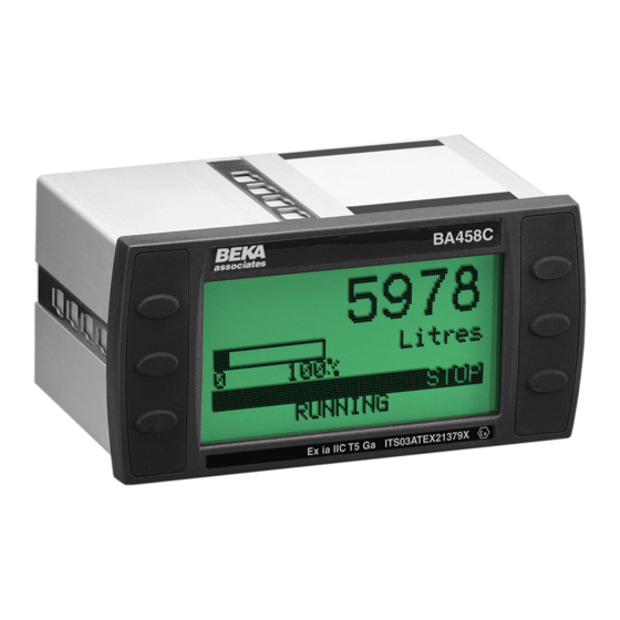
- Page 1 BA458C Intrinsically safe Panel mounting Batch Controller Issue 5 Issue: December 2010...
-
Page 2: Table Of Contents
Diagnostic Information menu 6.4.15 User screens 6.4.16 Display Appendix 3 FM & cFM Approval for use in USA & Canada. The BA458C is CE marked to show compliance with the European Explosive Atmospheres Directive 94/9/EC and the European EMC Directive 2004/108/EC... -
Page 3: Description
European Notified Body Intertek Testing Services (ITS) to the ATEX Directive 94/9/EC. The BA458C is also FM approved for use in the USA and cFM approved for use in Canada, these approvals are described in Appendix 3. Fig 1 Typical batch control application... -
Page 4: Operator Controls
Batch History shows the size of the modify the reset function. last ten batches which have been completed. Quick Restart eliminates the need to manually reset the BA458C at Configure function provides the end of each batch. When a operator... -
Page 5: Power Supply Failure
2.2 Power supply failure 3. INTRINSIC SAFETY CERTIFICATION If the power supply for the BA458C fails during a batch, the instrument will remember the 3.1 ATEX certificate quantity of product dispensed when the supply The BA458C has been issued with EC-Type... -
Page 6: Power Supply
–20 to +60 10.6V dc 20mA dc This allows the BA458C to be installed in all 0.05W Zones and to be used with most common industrial gases. They may also be connected to any device... -
Page 7: Switch Outputs
2.4mA dc those specified for simple apparatus in Clause 5.4 of EN50020:2002. This allows each of the BA458C switch outputs to be connected to any A wire link may be connected between the intrinsically safe circuit protected by a certified... -
Page 8: System Design For Hazardous Area
Any Zener barrier certified EEx ia IIC by an EEC approved certification body may be used, providing that the safety parameters are within the limits specified by the BA458C EC- Examination Certificate. Only one polarity of Zener barrier, i.e. positive or negative, may be used with each BA458C batch controller installation. - Page 9 12 & 11 4.2.2 Pulse inputs When programmed to operate with a proximity As shown in Figs 3 and 4 the BA458C batch detector, the maximum input frequency of the controller may be connected to a wide variety BA458C batch controller is 5kHz.
-
Page 10: Power Supply
1 & 2 should be connected to a 24V dc power supply via a WARNING 330Ω resistor. These switch outputs should not be used for critical safety applications. When the BA458C power supply is turned off or disconnected, all BA458C switch outputs will open. -
Page 11: Inputs
4.3.2 Inputs When the batch controller is powered from a galvanic isolator, the pulse and analogue inputs remain the same as described in sections 4.2.2 and 4.2.3. Only when the input transducer or source is in the safe area, as shown in Fig 7, are galvanic isolators required in the input circuit. -
Page 12: Inhibit Link
5.1 Location The BA458C is housed in a robust aluminium A certified intrinsically safe relay or a galvanic enclosure with a toughened glass window isolator with a switch contact output is required mounted in a Noryl bezel. -
Page 13: Installation Procedure
5.2 Installation Procedure a. Insert the BA458C into the instrument panel cut-out from the front of the panel. b. Fix panel mounting clips to opposite sides of the instrument and tighten until the instrument is secure as shown in Fig 10. -
Page 14: Configuration Menus
Functions offer a 6.2 Navigation choice of options or an invitation to enter a The BA458C is configured via the front panel variable. push-buttons which are soft-keys identified on the display screen. To select an option in a function menu... -
Page 15: Default Configuration
Clip-Off 00000.0 6.3 Default configuration Default parameters may be globally restored Unless otherwise requested at the time of see section 6.4.13 ordering, BA458C batch controllers will be supplied configured as follows: System Settings Language English Operator control Both Local &... - Page 16 Fig 11 System Settings...
-
Page 17: User Controls
See Fig 11. Note: Only necessary when 4/20mA input is used 6.4.1 Language When the BA458C batch controller is supplied The BA458C can display operating messages the analogue current input will have been and menus in three different languages: accurately... -
Page 18: Restart
Only available when factory fitted option is dispensed. Before another installed in the BA458C batch controller. batch can be started the Reset Configuration is the same as for Output 2, push-button must be operated. except terminal numbers are: The screen will then display ‘Ready’. - Page 19 If ‘Clear G Total’ is highlighted and the E 6.4.14 Security pushbutton operated, a second screen will be A summary of instrument security is contained presented. To confirm that the Grand Total is in section 6.1 of this manual. to be zeroed highlight ‘Continue’ and press E which will result in the instruction being This security function enables the four digit executed.
-
Page 20: Appendix 1
6.4.15 Operator Screens volume CONTROL2stop before Control 1 is The user screen may be selected from six de-energised. Fig. 1 shows the operation different formats that are shown in Appendix 1. diagrammatically. They show different information and have different display sizes so that the operator is 6.4.17.2 Control 3 only presented with the essential information This output is identical to Control 2 except... - Page 21 BLANK PAGE...
- Page 22 Fig 14 Batch Settings...
-
Page 23: Batch Settings
6.5 BATCH SETTINGS 6.5.2 Scale Factors (Non-linear pulse See Fig 14. inputs) The k factor of a flowmeter is the number of 6.5.1 Scale Points (Non-linear pulse inputs) output pulses that it produces per unit volume This and the following Scale Factors function e.g. -
Page 24: Scaling (4/20Ma Input)
Volume displayed = Number of input pulses The BA458C rate display represents litres per Scale Factor second but the total batched display is required in UK gallons. If the Scale Factor is set to the flowmeter’s k factor, the batch controller will display volume Scale Factor = Units of batched display in the flowmeter’s engineering units. -
Page 25: Batch Limit
6.5.7 Batch Limit 6.5.10 Select Batch To prevent accidental over-filling, the Batch This allows the batch controller’s operating Limit defines the maximum batch that may be setpoint to be selected from the nine pre- dispensed. If a batch setpoint greater than the entered setpoints. -
Page 26: Control2Stop
6.5.13 CONTROL2stop (Control 2 Pre-Stop) If the flow alarm has been assigned to one of Control 1 is de-energised when the batched the outputs, overrun compensation will be total equals the batch setpoint. Control 2 may calculated using product dispensed be de-energised at the same time, or a between Control 1 being de-energised and the programmable batch quantity before the batch... - Page 27 BLANK PAGE...
- Page 28 Fig 16 Rate Settings...
-
Page 29: Rate Settings
6.6.4 Rate Legend The BA458C batch display is in UK gallons but This function enables the units of the rate the rate display is required in litres. display to be entered. Up to six upper and... -
Page 30: Rate Filter
6.6.6 Rate Filter The BA458C contains a digital filter with two Smoothing: 2 independent adjustable parameters enabling Jump-Out: 4 the rate display frequency response to be tailored for optimum performance. 1..9 = Light..Heavy / 1..9 = Fine..Coarse Smoothing Amount of filtering applied (time constant). -
Page 31: Calibration Examples
7. CALIBRATION EXAMPLE The Operator Menu is not to be protected by a security code, but the Configuration Menus are In this example a BA458C batch controller is to be protected by code 1209. required to control the dispensing of a liquid into a tank as shown in Fig. - Page 32 Batch Settings Function Setting Scale Factor Batch D.P. 0000000.0 Batch Legend Litres Batch Limit 1050.0 Batch Names Batch 1 Full Volume Batch 2 Half Volume Batch Size Full Volume 1000.0 Half Volume 500.0 CONTROL2delay 10 seconds CONTROL2stop 50.0 Count Mode Overrun Comp Rate Settings Function...
-
Page 33: Fault Finding During Commissioning
User Controls pushbuttons do conditioned to configuration. not function. operate with If a BA458C fails after it has been functioning remote switches. correctly, the table shown in section 8.1 may BA458C will not Input not Signal input help to identify the cause of the failure. - Page 34 10. INDEX Subject Section Subject Section ATEX Directive 3.1, 3.8 Maintenance Menu Backlight 6.4.3, 6.4.16 Batch settings Batch Configuration Cycles 6.5.18 Operator Decimal point D.P. 6.5.5 Rate settings History 6.5.11 System Legend 6.5.6 Limit 6.5.7 Operator Names 6.5.8 Controls Select 6.5.10 Display 6.4.16...
- Page 37 APPENDIX 2 Information menu...
-
Page 38: Fm & Cfm Approval For Use In
FM Approvals, project identification 3033262. Copies Certificates of Compliance are available from the BEKA associates sales office, or may be downloaded from www.beka.co.uk A4.1 Intrinsic safety approval The BA458C batch controller is approved to the FM Class 3600 intrinsic safety Standard and Canadian Standard C22.2.
Need help?
Do you have a question about the BA458C and is the answer not in the manual?
Questions and answers