
Related Manuals for Snap-On EEWH315A


Summary of Contents for Snap-On EEWH315A
- Page 1 EEWH315A and 317A Air and Air/Electric Tire Changer Air et Air/Electrique Demont Pneus Operation Instructions Instruction opérationnel P/N: ZEEWHGB315A...
- Page 2 NOTE SULLA DOCUMENTAZIONE NOTES REGARDING DOCUMENTATION - ITA ENG - NOTAS SOBRE LA DOCUMENTACIÓN NOTES SUR LA DOCUMENTATION - SPA FRA - NOTAS SOBRE A DOCUMENTAÇÃO ANMERKUNGEN ZUR DOKUMENTATION - POR DEU - Product aid publication: Pubblicazione di supporto al prodotto: TIRE CHANGER SMONTAGOMME publication de support au produit:...
- Page 3 Fourth Edition 06/10 COPYRIGHT NOTICE The information contained in this document is property of Snap-on Incor- porated. It, or any of the information contained within, shall not be used, copied, or reproduced without express written consent of Snap-on TRADEMARK NOTICE...
- Page 4 EEWH315A and 317A Tire Changer Operation Manual U P D U P D U P DA A A A A T I N G G U I D E T I N G G U I D E T I N G G U I D E...
- Page 5 It is assumed that, prior to using the EEWH315A and EEWH317A Tire Changers, the operator has a thorough understanding of the wheels and tires being changed. In...
- Page 6 EEWH315A and 317A Tire Changer Operation Manual SAFETY INSTRUCTIONS IMPORTANT!! SAVE THESE INSTRUCTIONS!! Overinflated tires or tires mounted on the wrong sized rims can explode producing hazardous flying debris. • • • • • Read Operator’s Manual before using this Tire Changer.
- Page 7 EEWH315A and 317A Tire Changer Operation Manual Risk of crushing. Stand clear of bead breaker arm during operation. • • • • • Read and understand the operation instructions before using this Warning ! tire changer. • • • • • Become familiar with all controls before proceeding with operation.
- Page 8 EEWH315A and 317A Tire Changer Operation Manual Tires and rims that are not the same diameter are mismatched. • • • • • NEVER attempt to mount or inflate any tire and rim that are mismatched. • • • • •...
-
Page 9: Table Of Contents
EEWH315A and 317A Tire Changer Operation Manual --------------------------- GB --------------------------- TABLE OF CONTENTS SAFETY STATEMENTS ........................Page 5-8 TABLE OF CONTENTS ........................Page INTRODUCTION ........................Page 10 SPECIFICATIONS ........................Page 10 NOMENCLATURE ........................Page 10 1.2.1 FEATURES ..........................Page 11 MACHINE DIMENSIONS ...................... -
Page 10: Introduction
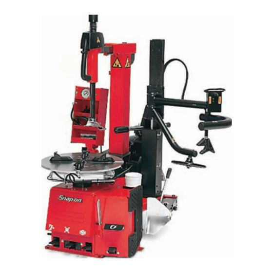
EEWH315A and 317A Tire Changer Operation Manual INTRODUCTION Congratulations on your purchase of the Snap-on EEWH315A and EEWH317A Series air, or air-electric tire changer. This tire changer is designed for ease of operation, safe handling of rims, reliability and speed. -
Page 11: Features
EEWH315A and 317A Tire Changer Operation Manual 1.2.1 TURNTABLE & CABINET FEATURES EEWH315A & 317A INTEGRATED BEAD SEATING JETS - Air inflation jets SAFETY RESTRAINT ARM (Optional) are integrated into the turntable clamping jaws to insure full bead seating force directly into the tire cavity TIRE/RIM ASSEMBLY RESTRAINT - Safety Restraint regardless of tire diameter. -
Page 12: Machine Dimensions
EEWH315A and 317A Tire Changer Operation Manual PNEUMATIC BEAD ASSIST ARM MACHINE DIMENSIONS Up/Down Control Switch - Toggle switch allows single finger operation of all pneumatic PBA functions, with or without gloves. Top Bead Roller - Provides easily controlled pneumatic... -
Page 13: Optional Accessories
EEWH315A and 317A Tire Changer Operation Manual #EAA0304G78A - Air Filter/Lubricator 1.5 OPTIONAL ACCESSORIES On Model EEWH315A #EAA0304G34A - Special jaws 8” ATV/Motorcycles #EAA0304G79A - Air Filter/Lubricator (Fig. 1.5-1) On Model EEWH317A (Fig. 1.4-2) Figure 1.4-2 1049 Figure 1.5-1 1.6 GENERAL CAUTIONS #EAA0247G06A - Replacement Mount/Demount A. -
Page 14: Installation
EEWH315A and 317A Tire Changer Operation Manual INSTALLATION 2.2 BEAD BREAKER INSTALLATION Your new Snap-on EEWH315A and EEWH317A Series The side mounted Bead Breaker could be shipped from Tire Changer requires a simple installation procedure the factory dismounted for a more compact shipping requiring only a few moments. -
Page 15: Controls
EEWH315A and 317A Tire Changer Operation Manual A. Connect the machine to the air supply with a rubber Before operating the machine, take the time to familiarize hose (rated for the pressure) with an internal diameter yourself with the operation and function of all the of no less than 1/2"... - Page 16 EEWH315A and 317A Tire Changer Operation Manual Press bead-seater pedal on left side of the PRESETTING OF CLAMPING JAWS machine (5, Fig. 3.0-1 / 1, Fig. 3.0-2) halfway down: This will allow activate the tire inflation line MAKE SURE ALL FOUR CLAMPING JAWS ARE POSITIONED IDENTICALLY (FIG.
-
Page 17: Mounting And Demounting Precautions
EEWH315A and 317A Tire Changer Operation Manual Position wheel and press it down by hand on the B. Break both beads. turntable. Hold open the Bead Breaker, roll the tire/rim into the Depress pedal through the first position and release. - Page 18 EEWH315A and 317A Tire Changer Operation Manual D. Liberally lubricate both beads. Place the wheel WITH MAINTENANCE NOTE: DROP CENTER UP (Fig. 4.1-3a) on the turntable, and IF THE MOUNT/DEMOUNT HEAD NYLON INSERTS clamp in position. It may be necessary to hold the tire...
-
Page 19: Mounting Tubeless Tires
EEWH315A and 317A Tire Changer Operation Manual H. Repeat the process for removing the lower bead. NOTICE! This time, lift the bead opposite to the mount/demount THESE LUBRICATION OPERATIONS ARE head to keep it in the drop center (Fig. 4.1-7). -
Page 20: Inflation Of Tubeless Tires
EEWH315A and 317A Tire Changer Operation Manual B. Lock the rim to the turntable and rotate it so that the 4.3 INFLATION OF TUBELESS TIRES. valve is at the 2 o’clock position. Place the tire to be mounted on the rim. Swing the mount/demount arm in Make sure that both beads are properly lubricated. -
Page 21: Demounting Tube Type Tires
EEWH315A and 317A Tire Changer Operation Manual (Fig. 4.3-1). 5.0 DEMOUNTING TUBE-TYPE TIRES Place the Nozzle against the rim edge NEVER STAND OVER TIRE WHEN ATTEMPTING A. For breaking the bead operate as described for the TO SEAT BEADS OR DURING INFLATION tubeless tires in section 4.1, point A to F. -
Page 22: Inflating Tube Type Tires
EEWH315A and 317A Tire Changer Operation Manual 5.2 INFLATING TUBE-TYPE TIRES. Make sure that both beads are properly lubricated. BEAD SEATING IS THE MOST DANGEROUS PART OF MOUNTING A TIRE. NEVER STAND OVER TIRE WHEN ATTEMPTING TO SEAT BEADS OR DURING INFLATION. - Page 23 EEWH315A and 317A Tire Changer Operation Manual 5.3 OPERATING THE PNEUMATIC BEAD ASSIST Depressor will be useful numerous times throughout the remount cycle. When remounting a tire the bead All Snap-on model EEWH315A & EEWH317A High depressor will ensure that the bead stays down in the...
-
Page 24: Mounting And Demounting Motorcycle Tires
EEWH315A and 317A Tire Changer Operation Manual have reseated after the bead breaking process and 5.4 MOUNTING AND DEMOUNTING MOTORCYCLE before tire removal. Secondarily the lower roller can be TIRES used to hold a wide tire up after the first bead has been removed. -
Page 25: Maintenance
EEWH315A and 317A Tire Changer Operation Manual 6.0 MAINTENANCE E. Lubricate piston rods of turntable air cylinders with oil as needed. BEFORE STARTING ANY MAINTENANCE OPERATION ENSURE THAT THE MACHINE IS F. Periodically wash all plastic parts with cold water... - Page 26 EEWH315A and 317A Tire Changer Operation Manual (BLANK PAGE) Page 26 Operation Manual...
- Page 27 EEWH315A et 317A Air et Air/Electrique Demont Pneus Instruction opérationnel P/N: ZEEWHGB315A...
- Page 28 EEWH315A et 317A Demonte Pneu Instruction Opérationnel (PAGE VIERGE) Page 28 Instruction Opérationnel...
- Page 29 Quatrième Édition 06/10 COPYRIGHT NOTICE The information contained in this document is property of Snap-on Incor- porated. It, or any of the information contained within, shall not be used, copied, or reproduced without express written consent of Snap-on TRADEMARK NOTICE and Snap-on Incorporated are registered trademarks Instruction Opérationnel...
- Page 30 EEWH315A et 317A Demonte Pneu Instruction Opérationnel (PAGE VIERGE) Page 30 Instruction Opérationnel...
- Page 31 électriques nécessaires à l’exécution du service au véhicule, en condition de sécurité. Avant d’utiliser le démonte-pneu EEWH315A et EEWH317A, se reporter toujours aux messages de sécurité et aux procédures de service fournis par les fabricants de l’équipement utilisé et du véhicule en réparation.
- Page 32 EEWH315A et 317A Demonte Pneu Instruction Opérationnel INSTRUCTIONS DE SÉCURITÉ IMPORTANT!! CONSERVER LES PRESENTES INSTRUCTIONS Les pneus surgonflés ou les pneus montés sur des jantes de taille non appropriée peuvent exploser et projeter des fragments. • • • • •...
- Page 33 EEWH315A et 317A Demonte Pneu Instruction Opérationnel Risque d’écrasement. Rester à distance de sécurité du bras de l’outil de décollage pendant le fonctionnement. Warning ! • • • • • Lire et comprend le manuel d’utilisation avant d’utiliser ce démonte-pneu.
- Page 34 EEWH315A et 317A Demonte Pneu Instruction Opérationnel Il n’est pas possible d’utiliser ensemble des pneus et des jantes de diamètre différent. • • • • • NE JAMAIS essayer de monter ou de gonfler un pneu et une jante de diamètre différent.
- Page 35 EEWH315A et 317A Demonte Pneu Instruction Opérationnel --------------------------- FR ---------------------------- INDEX Déclarations de la sécurité ..................... Page 31 INDEX ............................ Page 35 INTRODUCTION ........................Page 36 CARACTÉRISTIQUES TECHNIQUES .................. Page 36 TERMINOLOGIE ........................Page 36 1.2.1 CARACTERISTIQUES - AUTOCENTREUR ET CABINET ............ Page 37 DIMENSIONS DE LA MACHINE ....................
- Page 36 Vous pouvez intervenir sur des structures en alliages légers sans abîmer les roues de vos clients. Avec un minimum d’entretien et de soin, cet Snap-on EEWH315A et EEWH317A démonte pneu vous garantit de nombreuses années de travail rentable et sans problèmes.
- Page 37 EEWH315A et 317A Demonte Pneu Instruction Opérationnel 1.2.1 CARACTERISTIQUES - AUTOCENTREUR ET CABINET EEWH315A & 317A EMBOUTS DE MISE EN PLACE TALON INTEGRES ENSEMBLE BRAS DE MONTE/DEMONTE Le système de talonnage est intégré dans un jet buses pour assurer un plein effet talonnage directement dans RESERVOIR D’EQUILIBRAGE DE PRESSION DANS LA...
- Page 38 EEWH315A et 317A Demonte Pneu Instruction Opérationnel DES PRODUITS CONSTRUITS POUR DURER DIMENSIONS DE LA MACHINE VALVES ET CYLINDRES ANTIROUILLE Le cylindre critique de l’outil de décollage des bourrelets est garni d’un enduit antirouille assurant des années de fonctionnement sans rouille. L’utilisation de cylindres non garnis se traduirait par une perte de puissance de l’outil de...
- Page 39 EEWH315A et 317A Demonte Pneu Instruction Opérationnel #EAA0304G78A - Modèle ACCESSOIRES EN OPTION Filtre de l’air et Graisseur, EEWH315A #EAA0304G34A - Adaptateurs 8" moto/ATV #EAA0304G79A - (Figure 1.5-1) Filtre de l’air et Graisseur, Modèle EEWH317A (Fig. 1.4-2) Figure 1.4-2 1049 Figure 1.5-1...
- Page 40 2.2 FIXATION DU BRAS DETALONNEUR La procédure d’installation de ce démonte-pneu Snap- L’outil de décollage latéral est expédié démonté pour on EEWH315A et EEWH317A est simple et ne prend des raisons de volume de transport. que quelques minutes A. Couper la bande en plastique qui fixe le bras de Suivre soigneusement ces instructions en vue d’assurer...
- Page 41 EEWH315A et 317A Demonte Pneu Instruction Opérationnel Après avoir effectué tous ces contrôles, procéder Avant de travailler avec la machine, s’assurer d’avoir comme il suit: bien compris la position et les fonctions des commandes. (Figure 3.0-1). Relier la machine à la ligne de l’air comprimé, avec Appuyer et lâcher, la première pédale de...
- Page 42 EEWH315A et 317A Demonte Pneu Instruction Opérationnel / 1, Fig. 3.0-2) à mi-chemin. Cela permettra d’activer Les diamètres de la jante sont indiqués en pouces sur la ligne de gonflage du pneu l’autocentreur (A, Fig. 3.1-1). Le diamètre effectif paramétré (index sur le mors -B- situé à la hauteur de l’index sur l’autocentreur -A-) dépend aussi de la...
- Page 43 EEWH315A et 317A Demonte Pneu Instruction Opérationnel ÉVENTUELLEMENT APPLIQUÉES À L’INTÉRIEUR Effectuer cette opération avec beaucoup de précautions . DE LA JANTE. Eviter de maintenir trop longtemps la pédale du B. LE PNEU DOIT ÊTRE PROPRE ET SEC ET NI LE détalonneur pressée.
- Page 44 EEWH315A et 317A Demonte Pneu Instruction Opérationnel DIAMETRE JANTE, CE QUI ENTRAINE UN CONTACT INCORRECT DE L’INSERT AVEC LA JANTE. NOTE: QUAND L’OUTIL DE MONTAGE/DÉMONTAGE A ÉTÉ CORRECTEMENT POSITIONNÉ, LES ROUES IDENTIQUES PEUVENT ÊTRE MONTÉES SANS DEVOIR RÉGLER L’OUTIL DE NOUVEAU.
- Page 45 EEWH315A et 317A Demonte Pneu Instruction Opérationnel SEULEMENT DES LUBRIFIANTS SPÉCIFIQUES POUR PNEUS. DANGER!! Garder les mains et les doigts Fig. 4.1-7 à distance de la tête de montage/ démontage pendant l’opération. MONTAGE PNEUS SANS CHAMBRE (TUBELESS) NOTE! A. Nettoyer toute la surface de la jante (Fig. 4.2-1).
- Page 46 Pour répondre à ces problèmes Appuyer à fond sur la pédale de gonflage (1 Fig. 4.3-1) le modèle Snap-on EEWH315A et EEWH317A est équipé et le bouton du Bec Gicleur (3). Une grande quantité d’air d’injecteurs incorporés dans le Bec Gicleur, avec une bouton d’activation.
- Page 47 EEWH315A et 317A Demonte Pneu Instruction Opérationnel est expulsée par les injecteurs (4) et les talons adhèrent au bord de la jante en permettant le successif gonflage. NOTE: En même temps, l’air sort de l’extrémité du tuyau de gonflage (2) et du Bec (4).
- Page 48 EEWH315A et 317A Demonte Pneu Instruction Opérationnel 5.2 GONFLAGE PNEUS AVEC CHAMBRE. nécessaire pour éviter la formation de poches d’air entre la chambre à air et l’enveloppe) (Fig. 5.2-1). S’assurer que les deux talons soient bien lubrifiés. LA MISE EN PLACE DU TALON EST LA PHASE LA PLUS DANGEREUSE DU MONTAGE D’UN PNEU.
- Page 49 EEWH315A et 317A Demonte Pneu Instruction Opérationnel Fig. 5.3-1 Déplacer le rouleau talon dans la position au-dessus du Fig. 5.3-2 flanc des pneus. Pendant que la table tournante tourne, abaisser le rouleau au contact du flanc. Abaisser le talon Le troisième outil intégré dans le PBA est le rouleau talon de 1-2”.
- Page 50 flanc se soulève, la barre du pneu se met en place 6.0 ENTRETIEN facilement sur la tête de montage/démontage. AVANT DE COMMENCER TOUTE OPERATION 5.4 MONTAGE ET DÉMONTAGE PNEUS MOTO D’ENTRETIEN, S’ASSURER QUE LA MACHINE SERA DEBRANCHE DE LA RESEAU ELECTRIQUE Pour opérer sur les pneus pour moto il faut monter les ET DE L’AIR COMPRIME.
- Page 51 B. Nettoyer périodiquement tout les organes en métal des mouvement et lubrifier avec de l’huile. C. Nettoyer une fois par semaine les dents des griffes (A Fig. 6.0-2) avec une brosse en acier, contrôler les protections en plastique des dents des griffes (B) si celles-ci sont détériorées les remplacer.
- Page 52 No part of this document may be photocopied, reproduced, or translated without prior Snap-on written consent of Incorporated. is a registered trademark of Snap-on Incorporated. Avertissement: Les informations figurant dans le présent document peuvent faire l’objet de modifications Snap-on Snap-on sans préavis.
Need help?
Do you have a question about the EEWH315A and is the answer not in the manual?
Questions and answers