Table of Contents
Advertisement
Advertisement
Table of Contents

Related Manuals for Delta Electronics CTA4


Summary of Contents for Delta Electronics CTA4
- Page 1 Timer/Counter/Tachometer User Manual...
-
Page 2: Table Of Contents
Delta CTA series and assist the users to operate CTA as well as getting familiar with its functions. The date of the latest update is shown in the bottom left of the page. - Page 3 Make sure that you place the sensor, other input devices, signal cables and CTA away from the interference source. It will require 200ms after CTA is switched on for the activation of the internal power and default value reset. CTA may not operate normally during this period of time.
-
Page 4: Features
ASIC INSTRUCTIONS 1.1 Features Delta CTA series is the 3-in-1 timer, counter and tachometer with the following features: Can be a timer, counter, or tachometer and can operate in timer + counter mixed mode. Offers voltage input (PNP) or non-voltage input (NPN). -
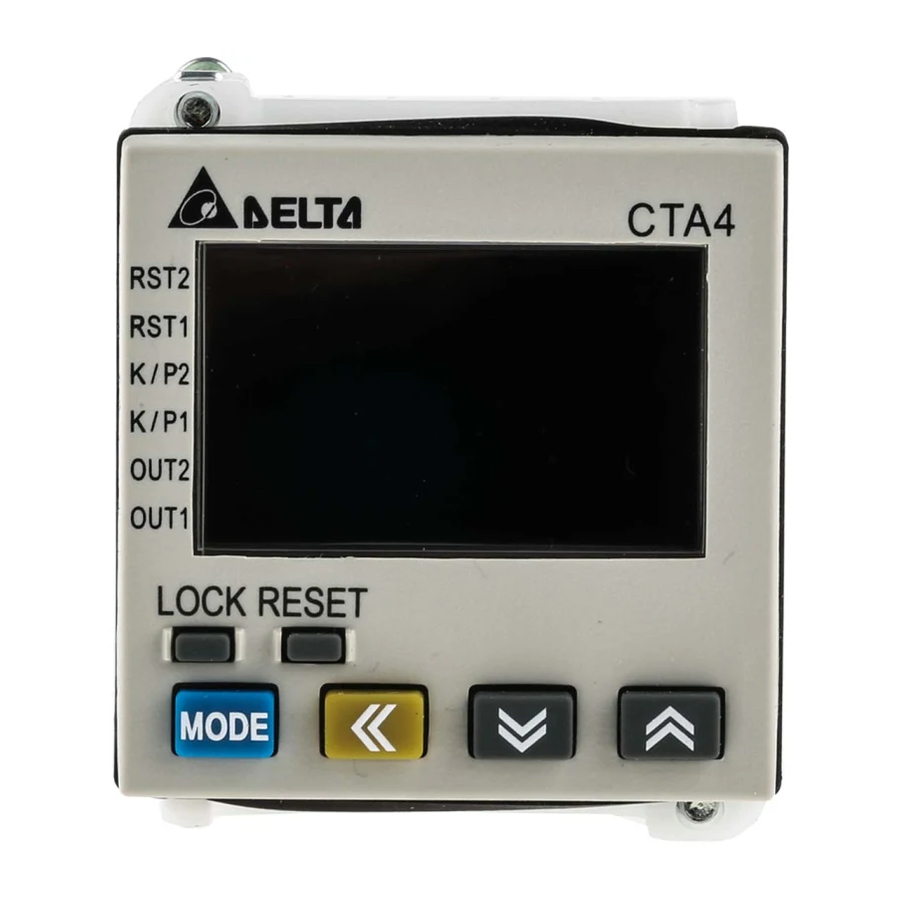
Page 5: Display, Indicators & Keys
1.6 Terminal Definition CTA combines the functions of timer, counter and tachometer; therefore, the definitions of input terminals in different modes are slightly different. CTA has 4 terminals ready for inputs. Take the pins in counter mode for example, (see figure 1). - Page 6 CTA for the connection. (Relay Output) 2007-05-09 Counter Timer Gate Reset1 Reset1 Reset2 Start Figure 1 (Transistor Output) - 6 - © DELTA ELECTRONICS, INC. ALL RIGHTS RESERVED Tachometer Timer + Counter Gate Reset1 Reset1 Start Figure 3...
-
Page 7: Default Settings
Input signal type 1.8 Easy DIP Switch Setup The tables below are the DIP switches for each mode of CTA. Please be noted that in the “timer + counter” mode, setting up parameters by DIP switches are not allowed. Timer... - Page 8 30cps 10Kcps 20ms Switch 3 Disabled Enabled See the table on the right 30Hz 10KHz 20ms - 8 - © DELTA ELECTRONICS, INC. ALL RIGHTS RESERVED Switch 4 Output mode Switch 4 Output mode Lo-Lo Lo-Hi Hi-Lo Hi-Hi...
-
Page 9: Timer
After the setup is completed, press page you are in and return to the main menu. Select functions: There are 4 modes in CTA, (left to right) timer, counter, tachometer and timer + counter. Select timer mode: counting up and counting down Select output modes: There are 12 output modes in the timer. - Page 10 If the clear signal is enabled (Hi) when the start signal is at rising edge, the output will stop immediately. - 10 - © DELTA ELECTRONICS, INC. ALL RIGHTS RESERVED...
- Page 11 Clear signal Output signal Down Power On Delay Hold © DELTA ELECTRONICS, INC. ALL RIGHTS RESERVED Signal On (Son) The start signal starts to time and output when the rising edge is triggered and the clear signal is not executed. When the set time is reached, the timer will return to the default value and the output will be disabled.
- Page 12 Power signal Start signal Pause signal Clear signal Output signal Down Timer output set as 0 - 12 - © DELTA ELECTRONICS, INC. ALL RIGHTS RESERVED Repeat Cycle timer output not set as 0 RCYH timer output not set as 0...
- Page 13 Pause signal Clear signal Output signal Down Signal Twin OFF-Start © DELTA ELECTRONICS, INC. ALL RIGHTS RESERVED CTA USER MANUAL Repeat Cycle2 (RCY2) Output in cycle. The start signal starts to time and output when the rising edge is triggered and the clear signal is not executed.
-
Page 14: Counter
Select input modes: counting up, counting down, command counting up/down, individual counting up/down, quadrature input Select output modes: CTA offer 11 output modes, among which mode S, T and D are only valid with input modes Ud_A, Ud_b and Ud_C. See 2.2.2 for more details. - Page 15 2.2.2 Setting up input mode of the counter CTA offers 5 counting modes: counting up, counting down, command counting up/down, individual counting up/down and quadrature input. The minimum signal width of the counting speed: Counting speed Minimum signal width 1cps...
- Page 16 Note: 2.2.3 Setting up output mode of the counter CTA offers 11 output modes in the counter for 1-stage and 2-stage counting. When 1-stage output is selected, output 2 and output 1 will be operated in the same way. Input mode...
- Page 17 There is only one SV in total counting. When the PV equals SV, the output will be enabled. If the clear signal is enabled now, the counting will restart and PV will be accumulated into the total counter. © DELTA ELECTRONICS, INC. ALL RIGHTS RESERVED Input mode...
- Page 18 2 will be enabled at the same time and the motor will be informed to move to the next package. This process will repeat and record the number of eggs packaged in the total counter for the user to check at any time. 2007-05-09 - 18 - © DELTA ELECTRONICS, INC. ALL RIGHTS RESERVED...
-
Page 19: Tachometer
2Hi1Lo, and assume the first set value is 100 (2Hi) and the second 50 (1Lo), the output value of the tachometer will be below 100 (2Hi) and above 50 (1Lo) and CTA will not perform an output. If the set value exceeds the range, CTA will perform an output. - Page 20 ※ = Number of pulses per revolution (ppr) Example 1: Connecting Delta servo drive with a servo motor and measure the current rotation speed by CTA The built in encoder in Delta servo motor is 10,000ppr with four phases, OA, OB, 2,500ppr.
- Page 21 At this time, the sensor detects the speed and sends it back to tachometer. Assume the value displayed on the screen is 3,200rpm, F × 60/3 = 3,200 F = 160Hz © DELTA ELECTRONICS, INC. ALL RIGHTS RESERVED Figure 1 - 21 - CTA USER MANUAL...
-
Page 22: Timer + Counter (Mixed Mode)
In this mode, the timer and counter both have a phase signal input; therefore, part of the functions will be limited. For example, there are 12 output modes for the timer of CTA, but only 8 output modes available in the timer + counter mode (Rcy2, Scon, Ston and Stoff are not available). -
Page 23: On Cut-To-Length Machine
3.1 On Cut-To-Length Machines The machine adopts the counter function in CTA and acquires the feedback signal from the encoder for measuring the actual operation distance. When the set distance is reached, the output signal will enable the knife for the cutting. - Page 24 CP1 (phase A) and Assume The set value in the CTA counter is 160mm. When the counting reaches 160mm, an output signal will be given to the knife for the cutting. See figure 2. In the figure, we can see the diameter of the roller is 44.8mm...
- Page 25 Figure 3 When the tachometer reaches 160mm, the output will be enabled. © DELTA ELECTRONICS, INC. ALL RIGHTS RESERVED Figure 4 The distance moved is 160mm. The ruler stops at 60mm. - 25 - CTA USER MANUAL Ruler at 60mm...
Need help?
Do you have a question about the CTA4 and is the answer not in the manual?
Questions and answers
Can i set the device to reset by itself the timer and counter values
Yes, the Delta Electronics CTA4 device has a "Reset" key that allows resetting the timer and counter values. Additionally, it provides a "Lock" key for more convenient use. The reset function can be triggered manually or by an external signal with a configurable reset signal width (e.g., 1ms or 20ms).
This answer is automatically generated
Cost of CTA4 Timer