
Related Manuals for National Instruments NI DIDS-2003


Summary of Contents for National Instruments NI DIDS-2003
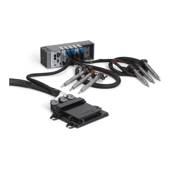
- Page 1 National Instruments Direct Injector Driver System NI DIDS-2003 NI DIDS-2006 NI DIDS-2009 NI DIDS-2012 NI Direct Injector Driver System User Guide May 2014...
-
Page 2: Table Of Contents
National Instruments Direct Injector Driver System Manual Table of Contents National Instruments Direct Injector Driver System ..................4 1. About the NI Direct Injector Driver System ..................5 2. Warnings ...............................6 2.1 REVERSE BATTERY POLARITY WARNING ................7 2.2 HIGH VOLTAGE WARNING ......................8 3. - Page 3 National Instruments Direct Injector Driver System Manual 4.6.3 Cam Phase Capture Tab ....................134 4.6.4 EPT Diagnostics Tab .......................137 4.7 Calibration Mode Setup Window ....................140 4.8 Table Setup Window ........................143 4.8.1 Table1D ..........................144 4.8.2 Table2D ..........................147 4.8.3 User Variables .........................150 4.9 Auxiliary PID Controller Setup Window ...................151 4.10 Rail Pressure Control Setup Window ..................157...
-
Page 4: National Instruments Direct Injector Driver System
National Instruments Direct Injector Driver System Manual National Instruments Direct Injector Driver System NI DIDS-2003 NI DIDS-2006 NI DIDS-2009 NI DIDS-2012 NI Direct Injector Driver System User Guide May 2014 © 2013 National Instruments. All rights reserved. -
Page 5: About The Ni Direct Injector Driver System
The NI Direct Injector Driver System comes in four different models corresponding to different direct injector channel configurations: the NI DIDS-2003 drives 3 solenoid injectors (or 2 piezoelectric injectors), the NI DIDS-2006 drives 6 solenoid injectors (or 4 piezoelectric injectors), the NI DIDS-2009 drives 9 solenoid injectors (or 6 piezoelectric injectors), and the NI DIDS-2012 drives 12 solenoid injectors (or 8 piezoelectric injectors). -
Page 6: Warnings
National Instruments Direct Injector Driver System Manual 2. Warnings Please read the following warnings for your safety and that of the product. © 2013 National Instruments. All rights reserved. -
Page 7: Reverse Battery Polarity Warning
National Instruments Direct Injector Driver System Manual 2.1 REVERSE BATTERY POLARITY WARNING NI Powertrain Controls power modules are not internally protected against reverse battery polarity. Do not reverse the battery polarity or damage will occur. This event is not covered under warranty. -
Page 8: High Voltage Warning
National Instruments Direct Injector Driver System Manual 2.2 HIGH VOLTAGE WARNING HIGH VOLTAGE: This device is capable of operating at voltages up to 190V. Extreme care should be taken to protect against shock. Even when the device is completely powered down, allow approximately five minutes for the internal high voltage to dissipate. -
Page 9: Getting Started
National Instruments Direct Injector Driver System Manual 3. Getting Started This guide will provide instructions to set up the National Instruments Direct Injector Driver System hardware and software. © 2013 National Instruments. All rights reserved. -
Page 10: What Is Included
National Instruments Direct Injector Driver System Manual 3.1 What Is Included Software DI Driver System software image preinstalled on the system controller NI Software Calibration Management Toolkit (SCM) for LabVIEW 2013, downloaded from www.ni.com. Hardware 1. Direct Injector Driver System... - Page 11 National Instruments Direct Injector Driver System Manual 3. Reverse Battery Protection Relay (P/N: 782784-01) 4. NI 9411 Module Breakout Harness(es) per NI 9411 Module (P/N: 782784-01) © 2013 National Instruments. All rights reserved.
-
Page 12: Software
National Instruments Direct Injector Driver System Manual 3.2 Software © 2013 National Instruments. All rights reserved. -
Page 13: Scm Software Installation
National Instruments Direct Injector Driver System Manual 3.2.1 SCM Software Installation Software Download At the time of shipping, the DI Driver System controller is pre-programmed with the latest version of software. However, in order to interact with the system, NI Software Calibration Management Toolkit (SCM) must be downloaded and installed to a PC with Windows 7 or newer. - Page 14 National Instruments Direct Injector Driver System Manual Download the LabVIEW 2013 version of the software. When prompted, choose the option to save the file NI_SCM_2013.zip. © 2013 National Instruments. All rights reserved.
- Page 15 National Instruments Direct Injector Driver System Manual Software Installation After the download is complete, browse to the location on disk where the file was saved. Extract the contents of the .zip file. After extracting the file, open the created directory and run the Setup.exe application. If prompted, install Microsoft .NET Framework 4.0.
- Page 16 National Instruments Direct Injector Driver System Manual From there, follow the instructions and prompts to finish installing the software. © 2013 National Instruments. All rights reserved.
-
Page 17: Connecting To The Di Driver System
National Instruments Direct Injector Driver System Manual 3.2.2 Connecting To The DI Driver System This section provides information about connecting to the DI Driver System user interface via SCM and how to change the network interface settings of the system controller. -
Page 18: Out Of The Box Connection
National Instruments Direct Injector Driver System Manual 3.2.2.1 Out Of The Box Connection This section describes how to establish a connection with the DI Driver System user interface via SCM. NI ships the DI Driver System with an IP address of 192.168.1.100 and a Subnet mask of 255.255.255.0. The Windows PC used to interface with the system must have a similar IP address and Subnet mask, but the IP address must be different in the last address number. - Page 19 National Instruments Direct Injector Driver System Manual 8. From the Local Area Connection Properties dialog, scroll down to select Internet Protocol Version 4 (TCP/ IPv4) and select the Properties button below the scroll window. 9. From the Internet Protocol Version 4 (TCP/IPv4) Properties dialog, select the Use the following IP address radio button.
- Page 20 National Instruments Direct Injector Driver System Manual 10. Open the NI SCM console from the Windows Start menu under National Instruments >> Software Calibration Management. 11. Within the SCM console, right-click inside the Target Items list pane and select Select Target.
- Page 21 National Instruments Direct Injector Driver System Manual 12. A dialog will open titled Search for SCM Target… If the Windows PC and the system controller have compatible network settings, then SCM will locate the DI Driver System on the network automatically. A Download Files checkbox will be presented within the dialog box and should be checked before pressing the OK button.
- Page 22 National Instruments Direct Injector Driver System Manual did not fully complete. If this is the case, please attempt the Search for SCM Target... step again. If the FTP download process fully completes, the green run button (2nd from left) will be enabled.
- Page 23 National Instruments Direct Injector Driver System Manual 15. If it is desired to change the network settings of the DI Driver System controller, refer to Changing The Network Settings Of The DI Driver System. © 2013 National Instruments. All rights reserved.
-
Page 24: Changing The Network Settings Of The Di Driver System
National Instruments Direct Injector Driver System Manual 3.2.2.2 Changing The Network Settings Of The DI Driver System This section assumes that a connection with the DI Driver System user interface is already established, and it is desired to change the IP address. If a connection has never been established, please refer to Out Of The Box Connection. - Page 25 National Instruments Direct Injector Driver System Manual If the Windows PC and the system controller are placed in DHCP mode and connected to a network router acting as a DHCP server, then both devices will be served IP addresses on the same subnet automatically.
-
Page 26: Manually Resetting The Controller Network Interface To Dhcp
National Instruments Direct Injector Driver System Manual 3.2.2.3 Manually Resetting The Controller Network Interface To DHCP This section assumes that all attempts have failed to establish connection with the DI Driver System user interface, and the system controller IP address is unknown. - Page 27 National Instruments Direct Injector Driver System Manual This will cause SCM to search the network for a National Instruments RT controller, such as the cRIO-9076 or cRIO-9022. If the DI Driver System controller is discovered, take note of the discovered IP address. The Windows PC used to interface with the system must have a similar IP address and Subnet mask as the system controller, but the IP address must be different in the last address number.
- Page 28 National Instruments Direct Injector Driver System Manual If the green and amber LEDs directly under the controller Ethernet port are not active or blinking, then there is no physical connection to a network router or PC, or there is no power to the controller. Please diagnose the Ethernet cable connection or controller power problem.
- Page 29 National Instruments Direct Injector Driver System Manual Note: NI does not recommend leaving DHCP mode for the DI Driver System controller because the IP address may change each time the system is powered. Each time the IP address changes, the Search for CalVIEW Target...
-
Page 30: Scm And Windows Firewall
National Instruments Direct Injector Driver System Manual 3.2.2.4 SCM and Windows Firewall After installing SCM, if Windows Firewall is enabled, SCM should be added to the list of Allowed Programs to communicate through the Windows Firewall. Since SCM must communicate with the DI Driver System via a Ethernet LAN port, it is important that Windows Firewall be configured to allow SCM, and its associated programs, access to the network. - Page 31 National Instruments Direct Injector Driver System Manual If Windows Firewall is on, and it is desired to turn it off, select Turn Windows Firewall on or off from the left menu and select the radio buttons as shown below. © 2013 National Instruments. All rights reserved.
- Page 32 National Instruments Direct Injector Driver System Manual To check the list of Allowed Programs, return to the main Windows Firewall window and select Allow a program or feature through Windows Firewall from the left menu. © 2013 National Instruments. All rights reserved.
- Page 33 National Instruments Direct Injector Driver System Manual Scroll through the list of programs and look for the following programs: SCM Console NI Backup and Restore NI SCM Calibration Difference NI SCM Calibration File Manager NI SCM Fault Display Confirm that both Home/Work (Private) and Public check boxes are checked. Select OK and close the Windows Firewall window.
- Page 34 National Instruments Direct Injector Driver System Manual © 2013 National Instruments. All rights reserved.
-
Page 35: Updating Di Driver System Controller Software
National Instruments Direct Injector Driver System Manual 3.2.3 Updating DI Driver System Controller Software Occasionally NI will generate updates to the DI Driver System controller software and provide a link to the latest update software on the DI Driver System product page. - Page 36 National Instruments Direct Injector Driver System Manual specified IP address. If the controller at the specified IP address is valid, then the Begin Update button at the bottom will be enabled. 6. Two options are available for selection before beginning the update process.
-
Page 37: Backing Up The Di Driver System Software Image
Select RT System dialog. 3. This will cause SCM to search the network for a National Instruments RT controller, such as the cRIO-9076 or cRIO-9022. Select the line associated with the system. Press OK to close the dialog and return to the Backup Target dialog. - Page 38 National Instruments Direct Injector Driver System Manual 4. The selected target IP Address should be listed in the IP Address field and additional target information will be shown in the Target Description field. 5. In the lower half of the Backup Target dialog, press the Backup Target button to browse the PC to specify the location to save the DI Driver System software image zip file.
-
Page 39: Restoring A Backup Image To The Di Driver System Controller
National Instruments Direct Injector Driver System Manual 3.2.5 Restoring A Backup Image To The DI Driver System Controller If the USER1 and USER FPGA LEDs are not blinking at all, please try pressing and immediately releasing the controller reset button. Wait 1 minute for the LEDs to start blinking. If they do not start blinking, follow the instructions below for restoring a backup image zip file to the system controller. - Page 40 National Instruments Direct Injector Driver System Manual 4. Select the line associated with the system. Press OK to close the dialog and return to the Restore Target dialog. 5. The selected target IP Address should be listed in the IP Address field and additional target information will be shown in the Target Description field.
- Page 41 National Instruments Direct Injector Driver System Manual 8. During the image restoration process, the PC cursor will indicate busy while hovering over the Restore Target dialog. The process will take about 3 minutes. 9. When the restoration process is completed, press the Back button to close the Restore Target dialog to return to the Real-Time System Backup dialog.
-
Page 42: Hardware
National Instruments Direct Injector Driver System Manual 3.3 Hardware © 2013 National Instruments. All rights reserved. -
Page 43: C-Series Module Slot Assignments
The NI DIDS-2003 DI Driver System includes a cRIO-9076 integrated controller and chassis with four slots. The slot assignments for the NI DIDS-2003 system are shown in figure 3.3.1.a, with the ability to add optional NI 9215 and NI 9758 (PFI Driver) modules (purchased separately). The DI Driver System software can only communicate with the modules when they are in their assigned slots shown in figure 3.3.1.a. - Page 44 National Instruments Direct Injector Driver System Manual Figure 3.3.1.a, 6-, 9-, and 12-Ch DI Driver System Configuration With Optional NI 9215 and PFI Driver *The NI 9215 and NI 9758 (PFI Driver) modules are optional modules that may be purchased separately. For more...
-
Page 45: Powering The System
National Instruments Direct Injector Driver System Manual 3.3.2 Powering the System Warning: The external battery supply input terminals on the NI 9751 (DI Driver) and NI 9758 (PFI Driver) modules are not reverse-voltage polarity protected. Connecting power to the module in reverse polarity will damage the modules. - Page 46 National Instruments Direct Injector Driver System Manual Power Wiring Guidelines NI recommends powering and grounding each component in the system in a star-wiring configuration, such that each component is wired individually from a single star-point for both positive and negative terminals of the power supply buses.
-
Page 47: Connecting Injectors, Sensors And Actuators
National Instruments Direct Injector Driver System Manual 3.3.3 Connecting Injectors, Sensors and Actuators © 2013 National Instruments. All rights reserved. -
Page 48: Direct Injectors To Di Driver Channels
National Instruments Direct Injector Driver System Manual 3.3.3.1 Direct Injectors to DI Driver Channels Connecting Direct Injectors to the Direct Injector (DI) Driver Module Direct injectors have two pins or wire leads. For solenoid injectors, the polarity of the injector leads typically does not matter. - Page 49 National Instruments Direct Injector Driver System Manual Figure 3.3.3.1.a, Diagram of Typical Wiring of Solenoid Injectors to a DI Driver Module Piezo Injector Wiring Driving piezo injectors requires in-series inductance on the high side wire (INJX+ wire) and shorting of channel 3.
-
Page 50: Port Fuel Injectors To Pfi Channels
National Instruments Direct Injector Driver System Manual 3.3.3.2 Port Fuel Injectors to PFI Channels The DI Driver System supports an optional PFI Driver module. The PFI Driver module has four channels, PFI1 – PFI4, for driving port fuel injectors. Each PFI driver channel is capable of driving low or high impedance port fuel injectors. - Page 51 National Instruments Direct Injector Driver System Manual Figure 3.3.3.2.a, Diagram of Typical Wiring of Port Fuel Injectors to a PFI Driver Module © 2013 National Instruments. All rights reserved.
-
Page 52: Proportional Solenoid Valves To Pfi Lowside Channels
National Instruments Direct Injector Driver System Manual 3.3.3.3 Proportional Solenoid Valves to PFI Lowside Channels The lowside drivers of the PFI Driver module are capable of driving a wide variety of automotive relays and proportional solenoid valves. Examples of actuators include EGR valves, turbocharger wastegate valves, fuel pressure regulators, or any single-solenoid-actuator which draws less than 1.5 amps. -
Page 53: Digital Signals To Ni 9411 Digital Input Module
National Instruments Direct Injector Driver System Manual 3.3.3.4 Digital Signals to NI 9411 Digital Input Module Each NI 9411 digital input module has six digital inputs. Each DI Driver System, regardless of number of DI Driver channels, contains at least one NI 9411 module in slot one (1). DIDS-2009 and DIDS-2012 systems contain an additional NI 9411 module in slot four (4). - Page 54 National Instruments Direct Injector Driver System Manual Direct Mode and TMP Mode Commands When operating DI Driver modules and/or the PFI Driver module in Direct mode or Triggered Multi-Pulse (TMP) mode, any of the NI 9411 digital input channels (up to 12) can be assigned to command any of the DI Driver and PFI...
- Page 55 National Instruments Direct Injector Driver System Manual Using ECU PFI or ignition driver outputs to command DI Driver System injection events requires that the DI Driver module or PFI Driver module be configured for Direct mode or TMP mode via the...
-
Page 56: Analog Signals To Ni 9215 Analog Input Module
National Instruments Direct Injector Driver System Manual 3.3.3.5 Analog Signals to NI 9215 Analog Input Module The DI Driver System supports an optional NI 9215 four-channel analog input module. The analog inputs are sampled at an interval of 15 milliseconds. The analog inputs are filtered and converted to engineering units via the Analog Input Setup window. -
Page 57: Di Driver System Component User Manual Reference
National Instruments Direct Injector Driver System Manual 3.3.4 DI Driver System Component User Manual Reference SCM User Manual NI 9076 User Manual NI 9022 User Manual NI 9114 User Manual NI 9411 User Manual NI 9215 User Manual NI 9751 (DI Driver) User Manual... -
Page 58: Using Di Driver System To Control Fuel Pressure
National Instruments Direct Injector Driver System Manual 3.4 Using DI Driver System to Control Fuel Pressure The DI Driver System supports a common rail pressure control feature with optional NI 9758 PFI Driver and NI 9215 analog input modules. A typical common rail high pressure fuel system consists of a high pressure, cam- drivven pump, connected to a fuel rail which supplies fuel to each injector. - Page 59 National Instruments Direct Injector Driver System Manual Figure 3.4.a, Diagram of Typical Wiring of an Inlet Metering Valve (IMV) and a High Pressure Valve (HPV) to a PFI Driver Module © 2013 National Instruments. All rights reserved.
-
Page 60: Optimizing The Di Driver System
National Instruments Direct Injector Driver System Manual 3.5 Optimizing The DI Driver System When connecting multiple injectors to a DI Driver System, there are a few optimizations to consider. Simultaneous or Overlapping Injection Events A DI Driver module uses multiplexed circuitry to provide up to three driver channels within the module for solenoid direct injectors and two channels per module for piezoelectric direct injectors. -
Page 61: Ni Direct Injector Driver System Interface
National Instruments Direct Injector Driver System Manual 4. NI Direct Injector Driver System Interface The main user interface window contains a list of all setup windows used to configure the various DI Driver System functions. Double-clicking on a setup window name will open the window and make the listed name bold. Multiple setup windows may be open simultaneously. - Page 62 National Instruments Direct Injector Driver System Manual SCM console buttons while DI Driver System user interface is closed SCM console buttons while DI Driver System user interface is open The DI Driver System can operate automatically, when powered up, according to settings saved to a system calibration file.
-
Page 63: Di Driver Setup Window
National Instruments Direct Injector Driver System Manual 4.1 DI Driver Setup Window The purpose of the DI Driver Setup window is to configure the Direct Injector (DI) Driver Module to the desired settings. A DI Driver System can have up to four DI Driver modules, DI1 through DI4. There is a... - Page 64 The maximum duration allowed is 5 msec. If longer durations are required, consult with your National Instruments sales engineer or support team. Calibration Mode: Calibration mode is for the purpose doing injector flow calibrations. Calibration mode...
- Page 65 National Instruments Direct Injector Driver System Manual DIX_ChanXEnable Tip Strip: Enables channel regardless of mode Detail: When ON, the associated channel is enabled to operate. DIX_OneShot Tip Strip: Generates one-shot command to selected channel Detail: When pressed, the DI Driver module will deliver a one-shot pulse to the channel selected in DIX_OneShotSelect, having a duration specified by DIX_OneShotTime.
- Page 66 National Instruments Direct Injector Driver System Manual DIX_BackBoostTime Tip Strip: Time period during which injector solenoid energy is directed back to the module boost power supply (after end of pulse) Units: msec Detail: The time period at the end of the injection pulse for which the back-electromotive force (EMF) of the injector solenoid is directed to the internal boost power supply.
- Page 67 National Instruments Direct Injector Driver System Manual IPhaseCurrentLower Tip Strip: Lower current dithering setpoint Units: Amps Detail: Lower threshold for current dithering set-point in Amps. IPhaseDuration Tip Strip: Duration of phase. 0 = hold to end of command. Units: msec Detail: Duration in milliseconds of each phase.
- Page 68 National Instruments Direct Injector Driver System Manual DIX_PiezoEnable Tip Strip: Enables piezo operating mode Detail: When ON, enables piezo injector operation. DIX_BackBoostTime will not be used and the control will be disabled. IPhaseArray is used differently in piezo mode. DIX_PiezoInvert Tip Strip: Enables inverted piezo operating mode Detail: When ON, enables inverted Piezo operation.
- Page 69 National Instruments Direct Injector Driver System Manual When DIX_ScopeRefresh is pressed, the graph will refresh with injector current, in Amps, during the most recent injection command to the associated DI Driver module. If multiple channels within the module are operating, it is not possible to identify which channel is being displayed. Note that the resolution of the current display is approximately 10 µsec sampling interval, and is for reference only.
- Page 70 24V, then the internal boost power supply will automatically shut down and rely on external power. Using an external high voltage supply is occasionally necessary, depending on injector operating requirements. Contact your National Instruments sales engineer or support team to determine if your application requires an external high voltage supply.
- Page 71 National Instruments Direct Injector Driver System Manual Detail: The DI driver module maintains an integrator of power supply usage. An internal counter increments with each internal power supply voltage boost and decrements according to a fixed time interval. If the integrator winds up to 100 percent, then an overload fault will be set.
- Page 72 National Instruments Direct Injector Driver System Manual DIX_FIXOpenCircuit Tip Strip: Injector open-circuit fault Detail: Indicates that the associated DI Driver channel cannot drive current above 1.5A at any point within the injection command. This is a non-critical fault and cannot be cleared. This fault does not interfere with injector channel operation.
-
Page 73: Di Driver Scope Window
National Instruments Direct Injector Driver System Manual 4.1.1 DI Driver Scope Window DIX_ScopeRefresh Tip Strip: Refreshes DI scope data Detail: When DIX_ScopeRefresh is pressed, the graph will refresh with injector current, in Amps, during the most recent injection command to the associated DI Driver module. If multiple channels within the module are operating, it is not possible to identify which channel is being displayed. -
Page 74: Pfi And Ls Driver Setup Window
National Instruments Direct Injector Driver System Manual 4.2 PFI and LS Driver Setup Window The purpose of the PFI and LS Driver Setup window is to configure the operation of the PFI Driver module. Three tabs are provided for the following:... -
Page 75: Pfi Module Control Tab
National Instruments Direct Injector Driver System Manual 4.2.1 PFI Module Control Tab The purpose of the PFI Module Control Tab is to enable the PFI Driver module, configure the operating mode, test PFI channels with one-shot pulses, and monitor module faults. - Page 76 National Instruments Direct Injector Driver System Manual PFI_ModuleEnable Tip Strip: Enables PFI Driver module operation Detail: If a PFI driver module is inserted in the assigned slot, externally powered, and PFI_ModuleEnable ON, then the controller begins communicating with the module and allows the module to operate.
- Page 77 National Instruments Direct Injector Driver System Manual Detail: When pressed, the PFI Driver module will deliver a one-shot pulse to the PFI channel selected in PFI_OneShotSelect, having a duration specified by PFI_OneShotTime. This button returns to the OFF state automatically.
- Page 78 National Instruments Direct Injector Driver System Manual Detail: Indicates that the current rise rate to the associated channel is indicative of a short circuit condition. This is a critical fault and will shut down the associated channel. PFI_OpenFaultOverride Tip Strip: Determines whether open-circuit faults are indicated Detail: When set to OVERRIDE, the open circuit faults will be ignored and will not be indicated.
-
Page 79: Pfi 1-4 Tab
National Instruments Direct Injector Driver System Manual 4.2.2 PFI 1-4 Tab The purpose of the PFI 1-4 tab is to enable individual PFI Driver PFI channels 1-4, and configure current control parameters. PFIX_FirstPeak Tip Strip: Causes phase 2 to begin after current reaches first peak Detail: A software option of the PFI Driver module to transfer operation from the first phase to the second phase upon reaching the first current peak corresponding to the first phase current setpoint. - Page 80 National Instruments Direct Injector Driver System Manual PFI Phase Setpoint & Duration Tip Strip: Current setpoint for this phase, Duration for this phase Units: Setpoint: Amps, Duration: msec Detail: These parameters configure the current and duration of the two phase within each injection command.
-
Page 81: Ls 1-4 Tab
National Instruments Direct Injector Driver System Manual 4.2.3 LS 1-4 Tab The purpose of the PFI LS 1-4 tab is to enable individual PFI Driver lowside (LS) channels 1-4, and configure their Pulse Width Modulation (PWM) parameters. Each LS channel is capable of 1.5A continuous. A special mode of operation is provided to combine current drive capacity among pairs of channels. - Page 82 National Instruments Direct Injector Driver System Manual PFI-LSX_ChanEnable Tip Strip: Enables lowside channel Detail: When ON, PFI-LSX channel is enabled for PWM operation. When PFI-LS12_Lock is ON, then PFI- LS2 parameters are not active because PFI-LS1 controls PFI-LS2. Likewise, when PFI-LS34_Lock is ON, then PFI-LS4 parameters are not active because PFI-LS3 controls PFI-LS4.
- Page 83 National Instruments Direct Injector Driver System Manual Detail: When ON, PFI-LS1 and PFI-LS2 channels are locked together for synchronous operation. This button is only active when both PFI-LS1 and PFI-LS2 channels are disabled. This rule ensures that LS channels one and two will be in lock sync when enabled.
- Page 84 National Instruments Direct Injector Driver System Manual PFI-LSX-TimingMode Tip Strip: Format of lowside PWM command Detail: Selects whether to use frequency or period parameters for PWM specification. PFI-LSX-ControlMode Tip Strip: Format of lowside PWM command Detail: Selects whether to use duty cycle or pulsewidth parameters for PWM specification.
- Page 85 National Instruments Direct Injector Driver System Manual PFI-LSX-PulseWidth Tip Strip: Pulse width of lowside PWM command Units: msec Detail: Specifies the pulsewidth of PWM operation for the associated PFI-LS channel. © 2013 National Instruments. All rights reserved.
-
Page 86: Digital Input Setup Window
National Instruments Direct Injector Driver System Manual 4.3 Digital Input Setup Window The purpose of the Digital Input Setup window is to configure the routing of NI 9411 digital input channels and four internally generated digital PWM signals to various destination functions of the DI Driver System. The window also shows the status of each NI 9411 digital input. - Page 87 National Instruments Direct Injector Driver System Manual six digital input sources associated with the 9411_1 slot are available. If there is only one NI 9411 module inserted in the 9411_2 slot, then only six digital input sources associated with the 9411_2 slot are available. DI Driver Systems using the cRIO-9076 chassis will only have one slot assigned for a NI 9411 module and the digital input sources associated with 9411_2 will not be available.
- Page 88 National Instruments Direct Injector Driver System Manual encoder patterns only. When the encoder is mounted to the crankshaft of a four-stroke engine, then a cam signal must be provided to mask every other encoder Z pulse (FALSE = Mask, TRUE = Pass). When the...
- Page 89 National Instruments Direct Injector Driver System Manual Digital Input Channel Signals Tip Strip: Digital input channel data and configuration Units: Frequency: Hz, Duty Cycle: %, Pulse Width: msec, Filter: µsec Detail: This display area shows the status of each NI 9411 digital input. The status parameters shown are: State, Frequency, Duty Cycle, and Pulse Width.
-
Page 90: Analog Input Setup Window
National Instruments Direct Injector Driver System Manual 4.4 Analog Input Setup Window The purpose of the Analog Input Setup window is to configure input processing of the analog signals to the NI 9215 Analog Input module. The window has four tabs. Each tab is associated with one channel of the NI 9215 and provides signal identification, monitoring, filtering, and conversion to engineering units. - Page 91 National Instruments Direct Injector Driver System Manual AIX_Raw Tip Strip: Raw voltage input Units: V Detail: Raw voltage signal sensed by the NI 9215 module. AIX_Conv Tip Strip: Calibration table Detail: 1D Lookup table for converting the analog input to engineering units. It is assumed that the conversion is linear and the table is 2x2.
- Page 92 National Instruments Direct Injector Driver System Manual Init_AIX_Filt Tip Strip: Re-intialize filter to change break frequency Detail: When pressed, reinitializes the 2 order filter on AIX_Raw. The filter should be reinitialized when changing AIX_FilterBreak. AIX_FilterBreak Tip Strip: Filter cutoff frequency...
-
Page 93: Pulse Generation Setup Window
National Instruments Direct Injector Driver System Manual 4.5 Pulse Generation Setup Window The purpose of the Pulse Generation Setup window is to configure injection command pulse sequences for the DI Driver modules and the PFI Driver module when configured for operating modes. -
Page 94: Di-Tmp Tab
National Instruments Direct Injector Driver System Manual 4.5.1 DI-TMP Tab The DI-TMP tab is for configuring Triggered Multi-Pulse (TMP) injection command pulse sequences with up to 6 pulses per sequence. Below is a timing diagram showing the effect of each parameter. An independent TMP command sequence is provided for each DI Driver module. - Page 95 National Instruments Direct Injector Driver System Manual TMP-OneShot_DIX_ChnX Tip Strip: Manually triggers TMP injection command sequence Detail: Pressing this button will trigger the configured TMP command sequence to the associated DI Driver module channel. The sequence will be triggered once with each button press.
- Page 96 National Instruments Direct Injector Driver System Manual Detail: Specifies the time duration of the injection pulse. The ON/OFF button above the Delay Duration parameters determines whether the pulse will be active or inactive. The control sends commands to Ch 1 if...
-
Page 97: Di-Ept Tab
National Instruments Direct Injector Driver System Manual 4.5.2 DI-EPT Tab The DI-EPT tab is for configuring EPT injection command pulse sequences with up to 6 pulses per sequence. Figures 4.5.2.a and 4.5.2.b, below, are timing diagrams showing the effect of each DIX Timing Mode parameter. - Page 98 National Instruments Direct Injector Driver System Manual SOI Timing Tip Strip: Start Of Injection angle with respect to TDC Units: DBTDC is set to SOI, this parameter specifies the Start of Injection (SOI) timing in Detail: When DIX Timing Mode Degrees before TDC.
- Page 99 National Instruments Direct Injector Driver System Manual Figure 4.5.2.b, Pulse Train for EOI Timing Mode. The reference timing is TDC position for each individual cylinder. Applicable to EPT mode. Duration Tip Strip: Duration of injection pulse Units: CAD Detail: This parameter is always disabled, but automatically updated with a calculated value. It is calculated...
- Page 100 National Instruments Direct Injector Driver System Manual Uniform/Individual DIX Channel Duration Enabled Indicator Tip Strip: Defines whether the DI Driver module is in uniform channel duration or individual channel duration mode. Detail: Shows the state of the Enable Individual DIX Channel Duration...
- Page 101 National Instruments Direct Injector Driver System Manual SkipFire_DI1_ChnX is enabled for the desired channel. Also manipulates and is manipulated by the corresponding SkipFire_OnCycle control in all the DIX Advanced Settings windows. DI Drivers 2-4 Detail: Please see information for DI Driver 1...
-
Page 102: Di Advanced Settings Window
National Instruments Direct Injector Driver System Manual 4.5.2.1 DI Advanced Settings Window The DI1 Advanced Settings Window allows users to configure individual channel durations for DI EPT injection command pulse sequences. The pulse enable and timing controls can be configured from this window, but they apply to all channels of the DI Driver module. - Page 103 National Instruments Direct Injector Driver System Manual Detail: When DIX Timing Mode is set to SOI, this parameter specifies the Start of Injection (SOI) timing in Degrees before TDC. When DIX Timing Mode is set to EOI, this parameter is disabled and retains its most recent value.
- Page 104 National Instruments Direct Injector Driver System Manual Duration Ch1 (msec) Tip Strip: Duration of injection pulse Units: msec Detail: Specifies the time duration of the injection pulse. The ON/OFF button above each Timing Duration parameter determines whether the pulse will be active or inactive.
- Page 105 National Instruments Direct Injector Driver System Manual Average Duration Detail: Displays the average duration of the injection commands for all three channels. SkipFire_DI1_ChnX Tip Strip: Enables Skip Fire on DI channel when EPT Mode is selected Detail: Enables the skip fire sequence defined by...
-
Page 106: Pfi Tab
National Instruments Direct Injector Driver System Manual 4.5.3 PFI Tab The PFI tab is for configuring both EPT and TMP operating modes for the PFI channels of the PFI Driver module. The EPT and TMP injection pulse command sequences support one pulse and apply it to all four PFI channels of the module. - Page 107 National Instruments Direct Injector Driver System Manual Duration Ch1 (msec) Tip Strip: Duration of injection pulse Units: msec Detail: Time duration of the EPT mode injection pulse. The ON/OFF button above each Timing Duration parameter determines whether the pulse will be active or inactive.
- Page 108 National Instruments Direct Injector Driver System Manual PFI1_SkipFire_OnCycle Tip Strip: Specifies the number of active cycles during skip fire sequence in EPT Mode (Min = 1). Detail: Specifies the number of active cycles included in a skip fire sequence when the PFI injector is operated in EPT mode.
- Page 109 National Instruments Direct Injector Driver System Manual TMP-OneShot_PFI_ChnX Tip Strip: Manually triggers TMP injection command sequence Detail: Pressing this button will trigger the configured TMP command sequence to the associated PFI Driver module channel. The sequence will be triggered once with each button press.
-
Page 110: Engine Position Tracking Setup Window
National Instruments Direct Injector Driver System Manual 4.6 Engine Position Tracking Setup Window The purpose of the Engine Position Tracking (EPT) Setup window is to configure angular position tracking of the engine crankshaft for supervising the generation of engine-synchronous injection commands. The... - Page 111 National Instruments Direct Injector Driver System Manual EPT Type Pattern Type Pattern Description Selections N-M patterns have N evenly spaced teeth and M missing adjacent teeth (gap) on the crankshaft trigger wheel. M is limited to 1 or 2 missing teeth. N is stated in terms of evenly spaced teeth, as if there were no missing teeth.
- Page 112 National Instruments Direct Injector Driver System Manual EPT function. This would cause the crank encoder pattern to effectively generate twice the teeth between each reference tooth seen by the EPT function. Table 4.6.a, Supported EPT Patterns Brief Glossary of EPT Function Terms CAD: Crank Angle Degrees.
- Page 113 National Instruments Direct Injector Driver System Manual It is often necessary to implement filtering of the crank and/or cam signals prior to entering the EPT function. The DI Driver System software provides an integrating filter function which rejects positive and negative digital signal pulses having a pulse width less than the filter time.
- Page 114 National Instruments Direct Injector Driver System Manual EPT Function Selection There are four EPT function selections available in the EPT_Type drop-down list. Each EPT function type is optimized for a particular range of number of crank teeth. For example, the DI Driver System provides two encoder pattern EPT functions, each optimized for different ranges of crank tooth counts.
- Page 115 National Instruments Direct Injector Driver System Manual The EPT function will lose sync in error when missing or extra crank/cam pulses are encountered where unexpected. In all conditions, when sync is lost, CrankCount will be set to 0 and SyncStopped will be set to “Stopped”.
- Page 116 National Instruments Direct Injector Driver System Manual STROKE. When tracking 720 degrees for 4-stroke engines, the camshaft input signal must be TRUE during every other crank tooth gap. This is designated by configuring the VI with Stroke = 4-STROKE. 2-Stroke Applications: Position 0 and tooth 0 coincide with the first tooth following each crank tooth gap.
- Page 117 National Instruments Direct Injector Driver System Manual Plus1 tooth. As another example, if the Plus1 tooth is retarded, and NumberOfCrankTeeth = 6, then CrankCount would increment from 0 to 5, such that tooth 5 would correspond to the tooth immediately after the Plus1 tooth and tooth 0 would correspond to the second tooth following the Plus1 tooth.
- Page 118 National Instruments Direct Injector Driver System Manual Figure 4.6.d, 6+1 (retarded) crankshaft trigger wheel tooth numbering Encoder Patterns Pattern Description: Encoder patterns have N evenly spaced teeth on the crankshaft with a separately sensed single reference (index, EncZ) tooth on the crankshaft or camshaft. The rising edge of the reference must occur between the same two crankshaft teeth rising edges each and every cycle.
- Page 119 National Instruments Direct Injector Driver System Manual EncZ signal may be inverted via the Digital Input Setup window to properly present a rising edge between the same two crank rising edges, each and every engine cycle. Research Engine Encoder Patterns: Optical encoders are a common source of signals for this pattern type in research applications.
-
Page 120: Ept Tab
National Instruments Direct Injector Driver System Manual 4.6.1 EPT Tab EPT_Type Tip Strip: Selects pattern type for the EPT function Detail: EPT function selection for pattern type and extrapolation level. Some pattern type selections only support one level of extrapolation due to the typical number of crank teeth for that pattern type. Refer to tables 4.6.a and 4.6.b in the... - Page 121 National Instruments Direct Injector Driver System Manual SyncEnable Tip Strip: Enables EPT to sync Detail: When ON, sync is enabled and position tracking will take place if valid crank and cam signal patterns are presented to the EPT function at an engine speed greater than the stall speed.
- Page 122 National Instruments Direct Injector Driver System Manual NumberOfCrankTeeth Tip Strip: Number of crank pulses per rotation Units: pulses Detail: Specifies the number of teeth on the crankshaft trigger wheel as if there were no missing or extra crank teeth. For example, a 60-2 crankshaft pattern would have NumberOfCrankTeeth = 60.
- Page 123 National Instruments Direct Injector Driver System Manual EngineStatus Tip Strip: Engine status based on StallSpeed and CrankRunThreshold Detail: Indicates the status of the engine crankshaft as stalled, cranking, or running, depending on the values StallSpeed and CrankRunThreshold. STALLED: Crank speed is less than...
- Page 124 National Instruments Direct Injector Driver System Manual CrankStalled Tip Strip: Indicates engine speed is below StallSpeed Detail: Indicates STALLED when the engine speed is below StallSpeed. Indicates SPINNING when the engine speed is above StallSpeed. SyncStopped Tip Strip: Indicates EPT is not in sync with engine Detail: Indicates STOPPED while position tracking is not taking place.
- Page 125 National Instruments Direct Injector Driver System Manual Detail: Set to FAULT upon the detection of a pattern-specific crank feature while the CrankCount value has not yet reached the expected value. Encoder Patterns: Indicates FAULT when an EncZ rising edge occurs before the expected number of Crank teeth have been counted.
- Page 126 National Instruments Direct Injector Driver System Manual AutoClearFlagWhileCranking Tip Strip: Auto-clears EPT errors during EngineStatus=CRANKING Detail: Sometimes, as the engine stops, the crankshaft may spin in a way that causes an erroneous loss of sync as the crankshaft comes to a rest and a fault flag will be set. This can often be prevented by increasing StallSpeed value.
- Page 127 National Instruments Direct Injector Driver System Manual CamExtEnable Tip Strip: Enables the cam signal to be extended by a specified number of crank pulses Detail: The DI Driver System provides an optional extension function applied to the cam signal selected by CamSelect.
- Page 128 National Instruments Direct Injector Driver System Manual Always Low: Indicated when the cam signal is constantly low upon each crank trigger wheel feature (M tooth gap or Plus1 tooth). An Error condition of the parameter does not cause a loss of sync.
- Page 129 National Instruments Direct Injector Driver System Manual Cam2 Tip Strip: Indicates state of the CAM signal Detail: Indicates the logic level of the digital input assigned to the Cam2 signal in the Digital Input Setup window. This indicator is not updated at the same rate the signal is changing. It is for reference only.
-
Page 130: Tdc Channel Mapping Tab
National Instruments Direct Injector Driver System Manual 4.6.2 TDC Channel Mapping Tab GlobalTDCOffset Tip Strip: Global TDC offset between absolute 0 and TDC1 Units: CAD Detail: Crank angle degrees between the EPT absolute zero position and TDC1. When TDC1 is before EPT... - Page 131 National Instruments Direct Injector Driver System Manual TDCX Tip Strip: Top Dead Center Units: CAD Detail: Crank angle degrees of offset between the TDC1 and TDCX, where X represents the cylinder number. Typically, engine cylinder #1 will have a TDC of zero because the...
- Page 132 National Instruments Direct Injector Driver System Manual DIX_Firing_Window_Start / DIX_Firing_Window_End Tip Strip: Start of angle-based window around all injection events for a channel, End of angle-based window around all injection events for a channel Units: DBTDC Detail: The three channels within a DI Driver module share driver circuitry and are multiplexed. Only one channel within a DI Driver module is able to operate at one time.
- Page 133 National Instruments Direct Injector Driver System Manual PFIX_TDC Tip Strip: Selects Top Dead Center reference associated with driver channel Detail: TDC parameters are mapped to a specific PFI Driver channel by selecting a TDCX from the drop- down list in each PFIX_TDC parameter, where X is the PFI Driver channel number.
-
Page 134: Cam Phase Capture Tab
National Instruments Direct Injector Driver System Manual 4.6.3 Cam Phase Capture Tab The purpose of the Cam Phase Capture Tab is to configure the cam-capture function and monitor the captured rising edges of each cam signal. This function is designed for Variable Valve Actuation (VVA) control. The PFI Driver module lowside driver channels can be used to implement PID control of VVA oil control valves. - Page 135 National Instruments Direct Injector Driver System Manual CamRE_TDC-Ref Tip Strip: Selects Top Dead Center reference associated with cam edge capturing Detail: Selects the TDCX reference for the CamX_Capture window. Cam1_Capture_Start Tip Strip: Start of angle-based capture window for cam signal...
- Page 136 National Instruments Direct Injector Driver System Manual Detail: The crank-angle location of a Cam1 signal rising edge, in Degrees Before TDC (DBTDC), captured in the window defined by Cam1_Capture_Start and Cam1_Capture_End. Cam2_Capture_Start Tip Strip: Start of angle-based capture window for cam signal...
-
Page 137: Ept Diagnostics Tab
National Instruments Direct Injector Driver System Manual 4.6.4 EPT Diagnostics Tab EPT Scope Tip Strip: Displays scope traces determined by setup Units: Samples Detail: Displays the logic level of each EPT function input. © 2013 National Instruments. All rights reserved. - Page 138 National Instruments Direct Injector Driver System Manual Scope Controls Tip Strip: Scope Controls, Update: Refreshes the EPT scope display, Clear: Clears the EPT scope display Detail: Used to manipulate the EPT Scope display and define cursors for measuring time and logic level of the various signals.
- Page 139 National Instruments Direct Injector Driver System Manual Detail: When pressed, the EPT diagnostic function will begin to acquire EPT signals. While the acquisition is running this control can be pressed again to abort the acquisition. Data Buffer Full Tip Strip: Indicates data stream is too fast and some samples may have been lost Detail: Indicates that the sampling rate is too fast for all samples to be recorded.
-
Page 140: Calibration Mode Setup Window
National Instruments Direct Injector Driver System Manual 4.7 Calibration Mode Setup Window The purpose of the Calibration Mode Setup window is to configure a series of uniform injection command pulses to the enabled channel of each DI Driver module. Only one channel of each DI Driver may be enabled at a time, otherwise no commands will be delivered to a module with multiple channels enabled. - Page 141 National Instruments Direct Injector Driver System Manual Detail: When pressed, pauses the delivery of the specified injection command sequence. When depressed, continues the command sequence at the paused location. Pausing the sequence will allow any active injection command to complete.
- Page 142 National Instruments Direct Injector Driver System Manual RemoteStartEnable Tip Strip: Enables remote start through External Digital Trigger Detail: Enables remote start through an external digital trigger configured by CalSeqStart_DigChanAsn. CalSeqStart_DigChanAsn Tip Strip: Selects the digital signal used for triggering the calibration sequence.
- Page 143 National Instruments Direct Injector Driver System Manual 4.8 Table Setup Window The purpose of the Table Setup window is to configure up to four one-dimensional (1D) lookup tables and up to four two-dimensional (2D) lookup tables for mapping input values to output values. A separate tab is utilized for each lookup table configuration.
- Page 144 National Instruments Direct Injector Driver System Manual 4.8.1 Table1D A 1D lookup table control consists of a set of matching X and Y arrays. The X values correspond to the input parameter as specified in Table1D_X_InputSelector. The 1D lookup table output is routed to the Flex Control Parameters selected in Table1D_X_FlexControlParameters.
- Page 145 National Instruments Direct Injector Driver System Manual Table1D_X_InputSelector Tip Strip: Assigns signal source to the 1D lookup table X array Detail: Drop-down selection control for selecting the input parameter for the X values of the lookup table. The available parameters for selection are analog inputs, battery voltage, digital input parameters, cam phase, engine speed, and user variables.
- Page 146 National Instruments Direct Injector Driver System Manual Table1D_X_FlexControlParameters Tip Strip: Selects destination of the 1D lookup table output Detail: Array of Flex Control Parameter selectors. Each selector maps the lookup table output to a Flex Control Parameter. The selected parameter will be overwritten by the lookup table output.
- Page 147 National Instruments Direct Injector Driver System Manual 4.8.2 Table2D A 2D lookup table control consists of a set of X and Y 1D input arrays and a matching Z 2D output array. The X values correspond to the input parameter as specified in Table2D_Xa_InputSelector. The Y values correspond to the input parameter as specified in Table2D_Xb_InputSelector.
- Page 148 National Instruments Direct Injector Driver System Manual Table2D_Xb_InputSelector Tip Strip: Assigns signal source to the 2D lookup table Y array Detail: Drop-down selection control for selecting the input parameter for the Y values of the lookup table. The available parameters for selection are analog inputs, battery voltage, digital input parameters, cam phase, engine speed, and user variables.
- Page 149 National Instruments Direct Injector Driver System Manual Detail: The left most X column (red) and the top Y row (blue) are for input. The 2D Z table values are triple interpolated to generate the lookup table output. © 2013 National Instruments. All rights reserved.
-
Page 150: User Variables
National Instruments Direct Injector Driver System Manual 4.8.3 User Variables Four Flex Control Parameters are available as general purpose variable storage. They are named UserVariable1 through UserVariable4. The User Variables Tab is used to document and manually specify the value of each user variable. -
Page 151: Auxiliary Pid Controller Setup Window
National Instruments Direct Injector Driver System Manual 4.9 Auxiliary PID Controller Setup Window The purpose of the Auxiliary PID Controller Setup window is for configuring up to four general purpose Proportional- Integral-Derivative (PID) controller functions for commanding a variety of Flex Control Parameters. The purpose of a PID controller is to manipulate a final output parameter in such a way that the error between the PID setpoint and the process variable is zero. - Page 152 National Instruments Direct Injector Driver System Manual AuxPIDX_EnablePID Tip Strip: Enables PID controller function AuxPIDX_ProcessVariableSelect Tip Strip: Select feedback variable for PID control Detail: Drop-down selection control for selecting the process variable input for the PID controller. The available parameters for selection are analog inputs, battery voltage, digital input parameters, cam phase, engine speed, and user variables.
- Page 153 National Instruments Direct Injector Driver System Manual AuxPIDX_Kc Tip Strip: PID proportional gain Detail: Proportional gain. A value of zero disables proportional, integral, and derivative contributions to the PID output. (See the equation above for reference.) Smaller values cause less proportional contribution to the PID output.
- Page 154 National Instruments Direct Injector Driver System Manual AuxPIDX Td_Action Tip Strip: Derivative contribution of PID controller Detail: Indicates the contribution of the derivative term to the total PID output. AuxPIDX_PIDMax Tip Strip: PID output maximum limit (before feed forward is added) Detail: Maximum output allowed from the PID controller.
- Page 155 National Instruments Direct Injector Driver System Manual Aux PID X Plot Tip Strip: Launches a plot displaying AuxPIDX_ProcessVariable, AuxPIDX_PIDSetpoint AuxPIDX_FinalOutput. AuxPID1_FlexControlParamWrite Tip Strip: Enables writing of PID final output to selected Flex Control Parameters Detail: When Enabled, enables the writing of the...
- Page 156 National Instruments Direct Injector Driver System Manual AuxPIDX_ManualOutput Units: % Detail: Value to override AuxPIDX_FinalOutput when AuxPIDX_ManualOverride is Enabled. AuxPID_X_FlexControlParam Tip Strip: Select flex control parameters to be controlled by this PID control Detail: Array of Flex Control Parameter selectors. Each selector maps the...
-
Page 157: Rail Pressure Control Setup Window
National Instruments Direct Injector Driver System Manual 4.10 Rail Pressure Control Setup Window The purpose of the Rail Pressure Control (RPC) Setup window, is to configure a dedicated direct injection common- rail fuel pressure control function. The function writes to the optional PFI Driver module lowside driver channels which are connected to a high pressure pump Inlet Metering Valve (IMV) and a High Pressure Valve (HPV) on the rail. - Page 158 National Instruments Direct Injector Driver System Manual Figure 4.10.a, Diagram of Typical Wiring of an Inlet Metering Valve (IMV) and a High Pressure Valve (HPV) to a PFI Driver Module PFI_ModulePresent Tip Strip: Indicates PFI Driver module present and externally powered Detail: Indicates that the system software detects that the PFI Driver module is externally powered and inserted in the assigned slot.
- Page 159 National Instruments Direct Injector Driver System Manual RailP_Max_Thresh Tip Strip: Rail pressure maximum threshold which causes a critical fault and shuts down associated PFI LSX channels Units: bar Detail: An upper threshold for rail pressure which defines a critical fault level that could potentially damage the fuel system.
- Page 160 National Instruments Direct Injector Driver System Manual RailP Tip Strip: Rail pressure in bar Units: bar Detail: Rail pressure used as feedback to the PID controller. The analog channel utilized for pressure feedback is selected via RailP_Channel. The analog channel must be converted to units of bar via the Analog Input Setup window.
- Page 161 National Instruments Direct Injector Driver System Manual IMV_Enable Tip Strip: Enables PWM control of IMV Detail: Enables the final PWM parameters to the lowside channels configured for IMV via the PFI and LS Driver Setup window. IMV_LSChanAsn Tip Strip: Indicates the PFI Driver lowside channels assigned to drive the IMV. The channel assignment is...
- Page 162 National Instruments Direct Injector Driver System Manual IMV_Ti Tip Strip: Integral time constant for IMV PID controller (lower = stronger action. 0 = disabled.) Units: min Detail: Integral time constant for the IMV PID controller. A value of zero disables integral contribution to the PID output.
- Page 163 National Instruments Direct Injector Driver System Manual IMV_PIDMin Tip Strip: IMV PID output minimum limit (before feed forward is added) Units: % Detail: Minimum output allowed from the PID controller, before the feed forward (IMV_PIDFF) is added. IMV_PIDFF Tip Strip: Duty cycle feed forward added to the IMV PID output Units: % Detail: Feed forward value that is added to the PID output value.
- Page 164 National Instruments Direct Injector Driver System Manual Detail: When ON, Cause the PID controller to be bypassed and sets PWM parameters for the IMV with a constant duty cycle defined by IMV_ManualDC. IMV_ManualDC Tip Strip: Value to override IMV PID final output when ManualOverride=TRUE...
- Page 165 National Instruments Direct Injector Driver System Manual IMV_NomResistance Tip Strip: Nominal resistance of IMV solenoid Units: Ohms Detail: Nominal resistance of the IMV solenoid. This value is used to calculate the maximum final duty cycle allowed to the IMV. It is important to measure this resistance within +/-0.5 ohms...
- Page 166 National Instruments Direct Injector Driver System Manual HPV_Kc Tip Strip: HPV PID proportional gain Units: %bar Detail: Proportional gain. A value of zero disables proportional, integral, and derivative contributions to the PID output. (See the equation in Auxiliary PID Controller Setup for reference.) Smaller values cause less...
- Page 167 National Instruments Direct Injector Driver System Manual HPV_Td_Action Tip Strip: Derivative contribution of HPV PID controller Detail: Indicates the contribution of the derivative term to the total PID output. HPV_PIDMax Tip Strip: HPV PID output maximum limit (before feed forward is added) Units: % Detail: Maximum output allowed from the PID controller, before the feed forward (HPV_PIDFF) is added.
- Page 168 National Instruments Direct Injector Driver System Manual HPV_PID Tip Strip: HPV PID controller output added to HPVPIDFF. Result is directed to selected PFI LS channel duty cycle parameter. Units: % Detail: Output value from the PID controller. This value is limited by the values in HPV_PIDMin HPV_PIDMax.
- Page 169 National Instruments Direct Injector Driver System Manual HPV_MinDC Tip Strip: Minimum allowed duty cycle for HPV Units: % Detail: Minimum allowed duty cycle for HPV HPV_DC Tip Strip: Final HPV duty cycle Units: % Detail: Final duty cycle applied to the HPV solenoid.
-
Page 170: Auxiliary Pwm Setup Window
National Instruments Direct Injector Driver System Manual 4.11 Auxiliary PWM Setup Window The purpose of the Auxiliary PWM Setup window is to configure up to four independent internally generated Pulse Width Modulation (PWM) signals to be assigned to digital input destinations via the Digital Input Setup window. - Page 171 National Instruments Direct Injector Driver System Manual AuxPWMX-Frequency Tip Strip: Frequency of PWM signal Units: Hz Detail: When AuxPWMX-TimingMode is set to Frequency, this field is enabled for specifying the time between rising edges of the PWM signal. AuxPWMX-DutyCycle Tip Strip: Duty cycle of PWM signal...
- Page 172 National Instruments Direct Injector Driver System Manual Aux PWX 2-4 See above descriptions. © 2013 National Instruments. All rights reserved.
-
Page 173: Operating Point Setup Window
National Instruments Direct Injector Driver System Manual 4.12 Operating Point Setup Window The purpose of the Operating Point Table Setup window is to configure two types of operation for automated test cycles: Timer Mode: Configure time-based, sequential operating points to be executed according to a specified time for each operating point. - Page 174 National Instruments Direct Injector Driver System Manual Detail: When ON, operating points are active according to the operating point table, and the table values will override the parameter values specified elsewhere within the DI Driver System setup windows. When OFF, the parameter values will remain set to the most recent values used from the operating point table. For...
- Page 175 National Instruments Direct Injector Driver System Manual Detail: Specifies the operating point which will be executed upon an error condition. This parameter is only applicable if Undefined Trigger Behavior is set to Goto Error State or Multiple Trigger Behavior is set to...
- Page 176 National Instruments Direct Injector Driver System Manual Undefined Trigger Behavior Tip Strip: Determines behavior when no trigger is present Detail: Selects the behavior of the operating points function while an operating point is not defined during Trigger Mode. This parameter is not applicable to Timer Mode.
- Page 177 National Instruments Direct Injector Driver System Manual Detail: When in Timer Mode, indicates when one or more of the Time fields have non-numeric characters entered, and the error state will be executed. When in Trigger Mode, indicates when one or more of the Wildcard fields have an invalid entry, and the error state will be executed.
- Page 178 National Instruments Direct Injector Driver System Manual Process Variables Detail: Array of drop-down selection controls for selecting the Trigger Mode process variable for each operating point. The available parameters for selection are analog inputs, battery voltage, digital input parameters, cam phase, engine speed, and user variables. Typically, all operating points would utilize the same process variable.
- Page 179 National Instruments Direct Injector Driver System Manual Detail: If Trigger Wildcard is blank, then the associated operating point is always satisfied. This type of Wildcard can be useful to specify a default operating point if it is used for operating point 0. If no other...
-
Page 180: Active Flex Control Parameters Window
National Instruments Direct Injector Driver System Manual 4.13 Active Flex Control Parameters Window The purpose of the Active Flex Control Parameters window is to show, within a single window, any Flex Control Parameters that are selected to be written by one of the DI Driver System software functions. Flex Control Parameters may be selected within the various setup windows, but the function may be optionally enabled or disabled. -
Page 181: Calscopes
National Instruments Direct Injector Driver System Manual CalScopes Window The purpose of the CalScopes window is to configure up to four oscilloscope-like displays for monitoring various software variables within the DI Driver System. This is an advanced feature which is documented within the user manual. -
Page 182: Caltrends
National Instruments Direct Injector Driver System Manual CalTrend Window The purpose of the CalTrend window is to configure up to eight multi-variable plot windows for monitoring various software variables within the DI Driver System. This is an advanced feature which is documented within the user manual. -
Page 183: Log Data Setup Window
National Instruments Direct Injector Driver System Manual 4.16 Log Data Setup Window The purpose of the Log Data Setup window is to configure data logging of a variety of DI Driver System software parameters to a text file, stored on the cRIO controller file system. The data files are NOT able to be logged over the network to another computer. - Page 184 National Instruments Direct Injector Driver System Manual Figure 4.16.a, FTP Browser Screenshot File Mode Tip Strip: Select to append new data to existing file data Detail: When set to Append, causes the Log Data function to append data to an existing file specified in the File Path.
- Page 185 National Instruments Direct Injector Driver System Manual Plot Buffer Length Tip Strip: Units: samples Detail: Specifies the number of samples to plot in the plot area to the right of the window. Sample Period Tip Strip: Should be in multiples of 50 msec...
- Page 186 National Instruments Direct Injector Driver System Manual Max Log Samples Units: samples Detail: When Stop Trigger is set to Number of Samples, data logging is stopped when the number of logged samples reaches the value specified by Max Log Samples.
- Page 187 National Instruments Direct Injector Driver System Manual Detail: Set to TRUE when an error is encountered during log file creation. Clear Errors Tip Strip: Select to clear log file fault Detail: Clears the error indicated by Log Write Error File Creation Error LEDs.
-
Page 188: Faults Window
National Instruments Direct Injector Driver System Manual 4.17 Faults Window The purpose of the Faults window is to show the status of each fault within the DI Driver System. The faults are displayed in alphabetical order. Hide Inactive Faults Detail: Filters the fault list to show only active faults. - Page 189 National Instruments Direct Injector Driver System Manual Ack All Detail: Acknowledges all active faults. Clr All Detail: Clears all active faults. Fault Count Detail: Indicates the number of active faults within each severity category. Fault Point Detail: The name assigned to the fault.
- Page 190 National Instruments Direct Injector Driver System Manual Severity Detail: Shows the severity of the fault. Sticky Detail: Indicates whether the fault is register as Sticky. When registered as Sticky, the fault will remain active for the time shown in Sticky Time.
- Page 191 National Instruments Direct Injector Driver System Manual Disable Detail: Double clicking the “Disable” cell associated with the fault will disable the fault from becoming active, even if the fault condition is present. © 2013 National Instruments. All rights reserved.
-
Page 192: Execution Information Window
National Instruments Direct Injector Driver System Manual 4.18 Execution Information Window The purpose of the Execution Information window is for diagnostic purposes. It is divided into three tabs titled Static Info, Network Run-Time Info. The first and third tabs show information about system configuration and software processes, respectively. -
Page 193: Static Info
National Instruments Direct Injector Driver System Manual 4.18.1 Static Info The Static Info Tab of the Execution Information window displays configuration information for the DI Driver System. © 2013 National Instruments. All rights reserved. -
Page 194: Network
National Instruments Direct Injector Driver System Manual 4.18.2 Network The Network tab of the Execution Information window displays the current network settings of the controller and allows the network settings to be changed. © 2013 National Instruments. All rights reserved. -
Page 195: Run-Time Info
National Instruments Direct Injector Driver System Manual 4.18.3 Run-Time Info The Run-Time Info tab of the Execution Information window displays the execution time of various software processes and parameters related to the controller hardware. © 2013 National Instruments. All rights reserved. -
Page 196: Troubleshooting
National Instruments Direct Injector Driver System Manual 5. Troubleshooting A Windows Help file (.chm) for the DI Driver System is provided on the cRIO controller along with the DI Driver System software image. The help file is downloaded from the controller to the computer along with the user interface windows when making the initial system connection. -
Page 197: Diagrams
National Instruments Direct Injector Driver System Manual 6. Diagrams Reverse Battery Relay Protection Diagram cRIO-9076 Slot Assignments © 2013 National Instruments. All rights reserved. - Page 198 National Instruments Direct Injector Driver System Manual NI 9114 Chassis Slot Assignments CompactRIO cRIO-9076 Front Panel © 2013 National Instruments. All rights reserved.
- Page 199 National Instruments Direct Injector Driver System Manual COMBICON power connector for cRIO-9076 CompactRIO cRIO-9022 Front Panel COMBICON power connector for cRIO-9022 © 2013 National Instruments. All rights reserved.
- Page 200 National Instruments Direct Injector Driver System Manual NI 9411 Pin and Terminal Assignments DI Driver Terminal assignments NI 9215 Driver Terminal assignments © 2013 National Instruments. All rights reserved.
- Page 201 National Instruments Direct Injector Driver System Manual PFI Driver Terminal assignments Use of Ferrules on Screw Terminal Connections © 2013 National Instruments. All rights reserved.
- Page 202 National Instruments Direct Injector Driver System Manual Connecting Solenoid Direct Injectors to the DI Driver © 2013 National Instruments. All rights reserved.
- Page 203 National Instruments Direct Injector Driver System Manual Connecting Piezo Direct Injectors to the DI Driver © 2013 National Instruments. All rights reserved.
- Page 204 National Instruments Direct Injector Driver System Manual Connecting Port Fuel Injectors to the PFI Driver © 2013 National Instruments. All rights reserved.
- Page 205 National Instruments Direct Injector Driver System Manual Connecting General Purpose Solenoids to the PFI Driver LS Channels © 2013 National Instruments. All rights reserved.
- Page 206 National Instruments Direct Injector Driver System Manual Connecting Inlet Metering/High Pressure Valves to the PFI Driver © 2013 National Instruments. All rights reserved.
-
Page 207: Additional Support/Feedback
National Instruments Direct Injector Driver System Manual 7. Additional Support/Feedback Please contact NI Systems Support at 210-248-9308 or powertraincontrolsinfo@ni.com. © 2013 National Instruments. All rights reserved. -
Page 208: Important Information
National Instruments Direct Injector Driver System Manual 8. Important Information © 2013 National Instruments. All rights reserved. -
Page 209: Warranty
The DIRECT INJECTOR DRIVER SYSTEM is warranted against defects in materials and workmanship for a period of one year from the date of shipment, as evidenced by receipts or other documentation. National Instruments will, at its option, repair or replace equipment that proves to be defective during the warranty period. This warranty includes parts and labor. -
Page 210: Copyright
National Instruments Corporation. National Instruments respects the intellectual property of others, and we ask our users to do the same. NI software is protected by copyright and other intellectual property laws. Where NI software may be used to reproduce software or other materials belonging to others, you may use NI software only to reproduce materials that you may reproduce in accordance with the terms of any applicable license or other legal restriction. -
Page 211: Trademarks
National Instruments Direct Injector Driver System Manual 8.3 Trademarks Refer to the NI Trademarks and Logo Guidelines at ni.com/trademarks for more information on National Instruments trademarks. ARM, Keil, and µVision are trademarks or registered of ARM Ltd or its subsidiaries. -
Page 212: Patents
National Instruments Direct Injector Driver System Manual 8.4 Patents For patents covering the National Instruments products/technology, refer to the appropriate location: Help»Patents in your software, the patents.txt file on your media, or the National Instruments Patent Notice at ni.com/patents. © 2013 National Instruments. All rights reserved. -
Page 213: Warning Regarding Use Of Ni Products
8.5 Warning Regarding Use of NI Products WARNING REGARDING USE OF NATIONAL INSTRUMENTS PRODUCTS (1) NATIONAL INSTRUMENTS PRODUCTS ARE NOT DESIGNED WITH COMPONENTS AND TESTING FOR A LEVEL OF RELIABILITY SUITABLE FOR USE IN OR IN CONNECTION WITH SURGICAL IMPLANTS OR AS CRITICAL COMPONENTS IN ANY LIFE SUPPORT SYSTEMS WHOSE FAILURE TO PERFORM CAN REASONABLY BE EXPECTED TO CAUSE SIGNIFICANT INJURY TO A HUMAN. -
Page 214: Environmental Management
National Instruments Direct Injector Driver System Manual 8.6 Environmental Management National Instruments is committed to designing and manufacturing products in an environmentally responsible manner. NI recognizes that eliminating certain hazardous substances from our products is beneficial not only to the environment but also to NI customers.
Need help?
Do you have a question about the NI DIDS-2003 and is the answer not in the manual?
Questions and answers