Table of Contents
Advertisement
Quick Links
aqua
computer
User and installation manual
User and installation manual
User and installation manual
User and installation manual
All information contained in this manual is subject to change without prior notice.
© 2020
VISION RGBpx
aquasuite version X.24
Current as of July 2020
All rights reserved.
Aqua Computer GmbH & Co. KG
Gelliehäuser Str. 1, 37130 Gleichen
VISION
ENGLISH: PAGE 1
DEUTSCH: SEITE 23
- 1 -
Advertisement
Table of Contents

Related Manuals for Aqua Computer VISION RGBpx

Summary of Contents for Aqua Computer VISION RGBpx
- Page 1 DEUTSCH: SEITE 23 Current as of July 2020 All information contained in this manual is subject to change without prior notice. All rights reserved. © 2020 Aqua Computer GmbH & Co. KG - 1 - Gelliehäuser Str. 1, 37130 Gleichen...
-
Page 2: Table Of Contents
Table of contents Table of contents 1. Preface..................3 2. Safety precautions.................4 3. Assembly instructions..............4 3.1. cuplex kryos sTRX4 with VISION RGBpx (21822)......4 4. Electrical connections..............4 4.1. USB cable..................4 5. aquasuite software................5 5.1. Installation of the aquasuite software..........5 5.2. Basic operation................5 5.3. -
Page 3: Preface
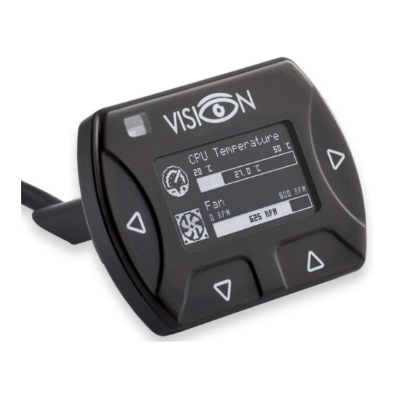
The VISION RGBpx module is a multi-purpose display and monitoring controller with integrated OLED display. As this manual covers all members of the VISION RGBpx series, some chapters of this manual will not apply to all product versions. Considering the fast technical development, we reserve the right to perform alter- ations to the products at any time. -
Page 4: Safety Precautions
Aqua Computer GmbH & Co. KG customers using or selling this product for use in such application do so at their own risk and agree to fully indemnify Aqua Computer GmbH &... -
Page 5: Aquasuite Software
Clicking the monitor symbol will toggle desktop mode for this overview page. While desktop mode is active, the color of the symbol will change to orange. © 2020 Aqua Computer GmbH & Co. KG - 5 - Gelliehäuser Str. 1, 37130 Gleichen... -
Page 6: Overview Pages (Aquasuite)
Click the symbol to add a new element to the page and select the desired element from the follow- - 6 - Aqua Computer GmbH & Co. KG © 2020 Gelliehäuser Str. 1, 37130 Gleichen... -
Page 7: Editing Existing Elements
Please refer to the next chapter for details. Once a chart has been configured, it can be selected from the “Chart selection” list on the “Display” tab of the settings dialog. © 2020 Aqua Computer GmbH & Co. KG - 7 - Gelliehäuser Str. 1, 37130 Gleichen... -
Page 8: User Defined: Images, Text, Drawing Elements
When importing complex pages with elements referring to more than one device, it is recommended to edit the device assignment in the file using a text editor prior to importing. - 8 - Aqua Computer GmbH & Co. KG © 2020 Gelliehäuser Str. 1, 37130 Gleichen... -
Page 9: Data Quick View And Data Log (Aquasuite)
This includes data from connected USB devices as well as hardware data supplied by the Aqua Computer background service. Displayed data may be filtered using the text box next to the magnifier icon, a chart shows the develop- ment over a maximum of ten minutes. -
Page 10: Manual Data Export
XML file on the hard disk or in the RAM (“memory mapped file”) in a regular time interval. The automatic data export will al- - 10 - Aqua Computer GmbH & Co. KG © 2020 Gelliehäuser Str. 1, 37130 Gleichen... -
Page 11: Sensor Configuration
Hardware temperature sensor Hardware temperature sensor The first sensor in the list represents the temperature sensor of the VISION RGBpx module. The temperature can be displayed either in degree Celsius of Fahrenheit. The log interval determines the time difference between sensor data continuously stored in memory and thereby the time period displayed in charts. -
Page 12: Display Configuration
9. 9. 9. 9. Display configuration Display configuration Display configuration Display configuration Select “Display” from the device list below the “VISION RGBpx” entry. In the upper area, the ten configurable display screens are displayed. In the lower area, the selected screen can be configured. 9.1. -
Page 13: Display Screens
Please note that the number of integrated LEDs depends on the product. Irrespec- tive of the product, 30 LEDs can be configured in the VISION RGBpx module, even if a lower number of LEDs is in fact integrated in the product. -
Page 14: Duplicate Led Controllers
Special features of the graphics card driver like “NVIDIA Surround” or “AMD Eyefinity” must be disabled. AMBIENTpx is not available while “NVIDIA G-Sync” is active. ● - 14 - Aqua Computer GmbH & Co. KG © 2020 Gelliehäuser Str. 1, 37130 Gleichen... -
Page 15: Alarm Configuration
VISION 11. Alarm configuration Alarm configuration Alarm configuration Alarm configuration Select “Alarms” from the device list below the “VISION RGBpx” entry. 11.1. 11.1. 11.1. 11.1. Alarm reporting and alarm limits Alarm reporting and alarm limits Alarm reporting and alarm limits Alarm reporting and alarm limits If desired, activate alarm monitoring and set an appropriate alarm limit. -
Page 16: Device Information
USB power supply USB power supply The VISION RGBpx module is supplied with power through the USB connection. In default configuration, power consumption is limited to a maximum current of 0.5 Amps. This value complies with the maximum allowed current according to the USB specification. -
Page 17: Playground (Aquasuite)
Buttons in the upper window area can be used to switch between global profiles. Alternatively, the profile icon in the title bar of the aquasuite window or a profile icon in the system tray may be used. © 2020 Aqua Computer GmbH & Co. KG - 17 - Gelliehäuser Str. 1, 37130 Gleichen... -
Page 18: Hotkeys
Click the entry “aquasuite web” to publish data on the internet or import data from the internet. The server for this service is operated by Aqua Computer and provid- ed for use with the aquasuite, without warranty for error free operation or perma- nent availability. -
Page 19: Data Access
Data import Data import To import a data set from the Aqua Computer server, the “access key” of the data set is required. The access key can be found in the aquasuite on the computer providing the data in the “Data access” section. -
Page 20: Units
Service administration Service administration The background service configures special USB settings for all connected Aqua Computer devices, provides hardware data, software sensors, pro- file management and aquasuite web and should therefore always be ac- tive. The hardware monitoring features of the background service can be disabled for specific categories if errors occur. -
Page 21: Technical Details And Care Instructions
“Register key” button, the update service period is permanently assigned to the selected device and stored on the Aqua Computer update server. The key will not have to be re-entered after re-installation of the software or transfer of the de- vice to another computer, but transferring the update service period to another de- vice is not possible. -
Page 22: Contact Aqua Computer
24/7. To get in direct contact with our customer support team, we offer several options: Email: support@aqua-computer.de Postal address: Aqua Computer GmbH & Co. KG Gelliehäuser Str. 1 37130 Gleichen Germany Tel: +49 (0) 5508 9749290 (9-16 h CET, German and English language) - 22 - Aqua Computer GmbH &...
Need help?
Do you have a question about the VISION RGBpx and is the answer not in the manual?
Questions and answers