Advertisement
Quick Links
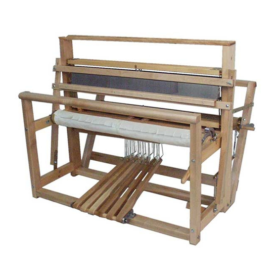
COMPACT 24"
4 SHAFTS
1022-0000
* Photos: Compact 8s
1573 Savoie
C. P. 4
Plessisville, Qc.
G6L 2Y6
TEL: 819-362-7207
FAX: 819-362-2045
www.leclerclooms.com
info@leclerclooms.com
On receiving the loom, unpack and
lay out the loom components.
Do NOT discard any packing material until
all parts are inventoried.
Check the parts received against the
parts list on pages #2 to #6 of the assembly
instructions. Report any discrepancies to
Leclerc immediately.
To assemble this loom, a minimum of 2
people are needed but it is recommended you
use 3.
Loom Prepared by:_____________
Inspected by:_________________
Date:____________________
.../compact4s.indd (2019)
1
Advertisement

Related Manuals for Leclerc Looms COMPACT 4 SHAFTS


Summary of Contents for Leclerc Looms COMPACT 4 SHAFTS
- Page 1 COMPACT 24” 4 SHAFTS 1022-0000 1573 Savoie C. P. 4 Plessisville, Qc. G6L 2Y6 TEL: 819-362-7207 FAX: 819-362-2045 www.leclerclooms.com info@leclerclooms.com On receiving the loom, unpack and lay out the loom components. Do NOT discard any packing material until all parts are inventoried. Check the parts received against the parts list on pages #2 to #6 of the assembly instructions.
- Page 2 1 frame with 4 shafts Pare-chocs sous cadres aminci 600 heddles 10½” 10½” 1 threading hook 1 red screwdriver & 1 Black 1 crank (Octagonal) Note for Leclerc in French : Enfiler les rondelles 3/16” 12 treadle cords 9” with dans chaque cordes et attacher washers 1/8”...
- Page 3 1 reed 2 lease sticks 25” (metal) 2 beam sticks 24½” (metal) 2 warp rods (metal) Cable de frein 25 1/16” Installer roulettes 1 right hand side front post (with brake cable) 44” 1 left hand side front post 44” 1 right hand side rear post 44”...
- Page 4 1 cloth beam 25” 1 warp beam 28 9/16” 1 thread beam 29 1/2” 1 left hand side cloth beam support 1 right hand side cloth beam support with ratchet pawl 10½” 4 side post iron fittings 3 treadle blocks 2 Wood pegs ½”...
- Page 5 2 batten swords 27¼” 6 treadles 20” 1 brake treadle 20” 1 treadle rod 5/16” x 30” 1 batten handtree 29” 1 batten sley 27¾” 1 breast beam 31”...
- Page 6 Machine bolts 1 X - 5/16” x 3” Carriage Bolts 2 X - ¼” x 2¾” (6mm x 70mm) 1" 2 X - 5/16 x 2¾” (8mm x 70mm) 2 X - 5/16” x 2” (8mm x 50mm) Metal Washers 2"...
- Page 7 Fix an iron fitting A on each of the 4 legs . Make sure they are positioned exactly as shown in the diagram below. Put a 3/16” (5mm) steel washer between the iron fitting and the leg. Screw them in using the 3/4” (20mm) round-headed screw No.
- Page 8 Place the loom frame on its right side. Fix the left front A and rear B legs to the left side of the frame with a 5/16” x 2¾” (8mm x 70mm) carriage bolt. With a hammer, hit on the head of the bolt until it is even with the leg B.
- Page 9 Lay down the frame (the bumpers must be on top) and pull on the lams C until the jacks D are parallel with the lams. Insert the left support E into the left end of the cloth beam F, then insert the take-up motion handle G and the right support H, into the right side of the cloth beam.
- Page 10 Place the loom on its right side and remove the handle B. Make sure the plastic spacer A is in place. Install first the rear leg iron fitting D and then the front leg iron fitting (fig.5). Screw back the handle into the lower position.
- Page 11 Fix the three (3) treadle blocks A to the treadle cross-member B with 2” (50mm) round-headed screws No. 14 (fig. 6). Note: Do not overtighten so blocks can move. Holes at this end of each treadle must be underneath Push nuts Assemble the treadle set as shown on figure 7.
- Page 12 Place the treadle set between the two (2) front legs by spreading them out slightly, so that the ends of the treadle rod A fit between the legs. Fix the treadle cross-member B with two (2) (50mm) round-headed screws No. 14. For installation with the wheels, use 2 flat headed screw #14 x 3 ½”.
- Page 13 Brake treadle Thread one end of the loop brake cord A into the hole of the brake treadle B, then thread one end of this cord into the second loop of the other end. Pull so that it makes a knot.
- Page 14 Machine bolt 5/16” x 3” (8mm x 75mm) Install the warp beam A between the two (2) back posts Screw a 5/16” x 3” (8mm x 75mm) machine bolt into the brake drum B. Use the crank D to tighten the bolt firmly.
- Page 15 Remove Saran wrap over the brake circle. Make sure that the friction brake parts are as this picture. Do not remove the black tape over the “S” hooks. Place the back beam next to the brake circle. Start passing over the brake drum, the brake circle.
- Page 16 Insert the machine bolt in the hole, align the warp beam and screw the bolt in the brake drum. Use the crank to screw until it is hard to turn. Attach the spring loop cord to the main castle screw at the black mark.
- Page 17 Install the thread beam (29½”) A using round-headed screws No. 14, 1½”. Install the lower cross-member B (30½”) in back of the loom with round-headed screws No. 14, 2”. For installation with the wheels, use 2 flat headed screw #14 x 3 ½”. Screw 1½”...
- Page 18 Fix each of the two (2) batten swords A inside the front legs with a 5/16” x 2” (8mm x 50mm) carriage bolt. Place a steel washer between the sword and the leg. With a hammer, hit on the head of the bolt until the square inside part is in the wood.
- Page 19 Place the reed A between the batten handtree B and the batten sley C, and lower the batten handtree. Tighten the wing nuts. Using a hammer, insert a batten stopper D (round piece of wood) into each of the two (2) swords E.
- Page 20 Install the breast beam A with two round-headed screws 1½” (40mm) No. 14. Make sure that the hole for the eyescrew is on the right side, more instruction on next page. Hole for the eyescrew for take-up motion handle Front Post Screw 1½”...
- Page 21 Screw the eyescrew in to the pre-drilled hole of the breast beam. Adjust the height of the take-up motion handle by changing the length of the loom cord.
- Page 22 Install treadle cords with the washers under the treadles as shown here Treadle cord with washer NOTE: This loom works better when all the treadles are connected to lams with tie-up cords. Tie-up cords prevent the lams from jamming as the shafts go down.
- Page 23 BEAMING 10 Yard Nylon Cord On this loom, beam sticks, metal rods and cords have to be installed in place of the usual apron. Warp Beam Thread a 10 yard (9.2m) nylon cord through the third set of holes of the warp beam.
- Page 24 To install the heddles you can just bend the heddle supports . To remove the shaft frames you first have to unscrew the top nut of the jack pin. It is important to leave the bottom nut as it is. Then pull up the shaft frame from the castle.
- Page 25 Warp beam advance control system Install the Warp beam advance control system. This system will eliminate excessive warp yarn advance when releasing the brake system at cloth take-up. have to be released when This friction system is adjustable and winding the warp on. Just screw the wing nut with nylon bolt in the pre-install metal indert of the left back post.
-
Page 26: Maintenance
To fold the loom, Disconnect the friction brake loop cord from the screw (S), release the tension by pressing the brake treadle, then loosen the plastic handles on each side of the loom and pull these upward. Tighten the handles. The loom can fold even with fabric on it.
Need help?
Do you have a question about the COMPACT 4 SHAFTS and is the answer not in the manual?
Questions and answers