Advertisement
Quick Links
Advertisement

Subscribe to Our Youtube Channel
Related Manuals for AVANT B105


Summary of Contents for AVANT B105
- Page 1 B105/B155/B230 Hydraulic breaker...
- Page 2 Table of contents hydraulic breaker TABLE OF CONTENTS OPERATION ........................3 1.FOREWORD................................4 1.1 IMPORTANT SAFETY INFORMATION ......................4 1.2 WARRANTY ..............................5 1.3 SPARE PART ORDERS............................5 2. MACHINE NUMBERS ............................6 2. 1 MODEL AND SERIAL NUMBER........................6 3. PRODUCT INTRODUCTION ..........................7 3.1 OVERVIEW ................................7 3.2 REMOVAL FROM PACKAGE ..........................7 3.3 LIFTING INSTRUCTIONS ..........................7 3.4 MAIN PARTS..............................9...
- Page 3 hydraulic breaker Operation...
- Page 4 Foreword hydraulic breaker Basic safety precautions are outlined in the "Safety" section of this manual and in the description of operations where hazards exist. Warning labels have also been put on the machine to provide instructions and to identify specific hazards which if not observed could cause bodily injury or death to you or other persons.
- Page 5 hydraulic breaker Warranty A complete warranty claim for a hydraulic breaker attachment includes at least the following information. Model and serial number Carrier model Working hours and service history Installation: Oil flow, operating pressure and return line pressure if known Application Providing this information makes it easy to handle the warranty claim prop- erly and swiftly.
- Page 6 Machine numbers hydraulic breaker The equipment serial number is stamped on the valve body. The model and serial number are also located on the CE marking. Check that the model cor- responds to the one given on the cover of this manual. It is important to make correct reference to the serial number of the attach- ment when making repairs or ordering spare parts.
- Page 7 Product introduction The product is a hydraulically operated breaker. It can be used on all AVANT-carriers which meet the necessary hydraulic and mechanical installation re- quirements. The unit functions by repeatedly raising a steel piston and driving it down onto the head of a removable breaking tool.
- Page 8 Product introduction hydraulic breaker Lifting devices must safely carry the working weight of the product. See “Hammer specifications” on page 48. Place chains or slings, as shown by the illustration, to lift the product. Below are some common safety instructions concerning lifting operations. In addition to this, the local, national standards for machines and lifting-tack- les must always be strictly observed.
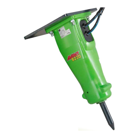
- Page 9 hydraulic breaker Product introduction The main parts of the hammer are shown below. A. Side plates B. Mounting flange C. Accumulator D. Hammer mechanism E. Hose connections F. Grease nipples...
- Page 10 Safety hydraulic breaker All mechanical equipment can be hazardous if operated without due care or correct maintenance. Most accidents involving machine operation and maintenance are caused by failure to observe basic safety rules or precau- tions. An accident can often be avoided by recognizing potentially hazard- ous situations before an accident occurs.
- Page 11 hydraulic breaker Safety The related safety label on the hammer and the text on the label are shown here. All the time you are working with the product, take care and stay alert. Al- ways be alert for hazards. The possibility of a serious or even fatal accident is increased when you are intoxicated.
- Page 12 Safety hydraulic breaker Work sites can be hazardous. Inspect the site before working on it. Check for potholes, weak ground, hidden rocks etc. Check for utilities (elec- tric cables, gas and water pipes etc.). Mark the positions of underground ca- bles and pipes if you will be breaking the ground.
- Page 13 hydraulic breaker Safety Stop working, when bystanders are in the area of airborne pollutants and make sure they have proper respirators. Respirators are as important for bystanders as hard hats.Respirators for both operator and bystanders must be approved by the respirator manufacturer for the application in question. It is essential that the respirators protect from the tiny dust particles which cause silicosis and which may cause other serious lung diseases.
- Page 14 Safety hydraulic breaker Operating the product beyond its design limits can cause damage. It can also be dangerous. See “Hammer specifications” on page 48. Do not try to enhance the product's performance by unapproved modifica- tions. Fine jets of hydraulic fluid at high pressure can penetrate the skin. Do not use your fingers to check for hydraulic fluid leaks.
- Page 15 hydraulic breaker Safety The safety label on or near the accumulator is shown here: The hammer incorporates one or two pressure accumulators, depending on the model. The accumulators are pressurized even when there is no hydraulic pressure to the hammer. Attempting to dismantle the accumulators without first releasing the pressure can cause injury or death.
- Page 16 Safety hydraulic breaker You can be injured by flying splinters when driving metal pins in and out. Use soft-faced hammer or drifts to remove and fit metal pins, such as pivot pins. Always wear safety glasses. Safety labels communicate the following four things: •...
- Page 17 hydraulic breaker Safety...
- Page 18 Operation hydraulic breaker The hammer is designed to be used in breaking concrete, road surface or asphalt, hard or frozen ground. It is also suitable for light trenching and benching applications or in ground compacting. It can be also used in break- ing small and soft boulders.
- Page 19 hydraulic breaker Operation Impact breaking With impact breaking, the material is broken by transferring very strong mechanical stress waves from the tool into the material. Impact breaking is most effective in hard, brittle and very abrasive materials. The high impact energy of the big hammers makes them ideal for impact breaking.
- Page 20 Operation hydraulic breaker 1. Set the engine speed to the recommended engine RPM for correct amount of oil supply. 2. Carefully operate the carrier controls to place the hammer and boom into the breaking position. Quick and careless boom movements could result in damage to the hammer.
- Page 21 hydraulic breaker Operation 7. A safety screen is recommended to protect the operator from flying debris. Keep the cabin windows and doors closed during operation. 8. Note: Listen to the hammer's sound when you are using it. If the sound becomes weaker and the impact less efficient, the tool is misaligned with the material and/or there is not enough down force on the tool.
- Page 22 Operation hydraulic breaker 13. Stop the hammer quickly. Do not allow the hammer to fall down and make idle strokes when an object breaks. Frequent idle strokes have a deteriorating effect on the hammer. If the hammer falls through, the housing wears out more quickly.
- Page 23 hydraulic breaker Operation 17. Do not use the hammer or hammer tools for lifting. (see picture 8) 18. The tool shank must be well greased during operation. Regular visual in- spections during operation are recommended. An unlubricated tool shank requires more frequent greasing intervals. A tool shank covered with excessive grease requires less frequent greasing intervals.
- Page 24 Operation hydraulic breaker Stage 1: • Lift up the two locking pins on both sides of the attachment coupling plate and turn them backward so that they remain in the up position • Make sure that the pins remain in the up position, otherwise you cannot couple the attachment properly! Stage 2: •...
- Page 25 hydraulic breaker Operation The transportation and parking positions are shown below. When moving with the hammer, ensure that the hammer is not too close to the ground. Also make sure that you see the tip of the tool at all times. 1.
- Page 26 Operation hydraulic breaker Observe the following points when the hammer is stored. In this way the vital parts of the attachment are protected from rust and the machine is ready to be used whenever necessary. 1. The storage area must be dry. 2.
- Page 27 hydraulic breaker Lubrication...
- Page 28 Hammer tool greasing hydraulic breaker For tool lubrication use a grease that meets the following criteria: • No dropping point or very high, over 250 °C (480 °F). • Maximum service temperature at least 150 °C (300 °F). • Minimum working temperature below lowest ambient temperature. •...
- Page 29 hydraulic breaker Hammer tool greasing Insufficient greasing or improper grease may cause: l Abnormal wear of tool bushing and tool l Tool breakage 1. Position the hammer standing upright resting on the tool on firm surface. 2. Stop carrier engine and wait 10 minutes for oil pressure to drop inside hammer.
- Page 30 The machine must be moved to bring the oil tem- perature above 0 °C before hammering can start (viscosity 1000 cSt or 131 °E). AVANT Recommends: Shell tellus TX46 in normal conditions. Shell tellus TX68 when ambient temperature exceeds 35 °C.
- Page 31 hydraulic breaker Carrier hydraulic oil Table below shows hydraulic oils recommended for hammer use. The most suitable oil is selected in such a way that the temperature of the hydraulic oil in continuous use is in the ideal area on the chart and the hydraulic system is used to best advantage.
- Page 32 35 °C. The correct hydraulic oil viscosity is thus ensured. Make sure that the AVANT carrier is equipped with an oil cooler before installing the hammer.
- Page 33 hydraulic breaker Maintenance...
- Page 34 Routine maintenance hydraulic breaker This product is a precision made hydraulic machine. Therefore great care and cleanliness should be taken when handling any of the hydraulic compo- nents. Dirt is the worst enemy in hydraulic systems. Handle the parts carefully and remember to cover any cleaned and dried parts with clean lint-free cloth.
- Page 35 hydraulic breaker Routine maintenance Note: The time intervals given refer to the carrier hours while the attachment is installed. t is recommended to have the first inspection done by your local dealer after 50 to 100 operating hours. Contact your local dealer for more information about the initial 50-hour inspection.
- Page 36 Routine maintenance hydraulic breaker When working with attachment and removing it from the carrier, dirt (mud, rock powder etc.) can become attached to it. Wash the outside of the product with a steam washer before sending it to the workshop. Dirt can cause difficulties in disassembly and assembly otherwise.
- Page 37 Removal of tool Model B105 B155 B230 Tool diameter (worn out) 38 mm 46 mm 54 mm Tool and tool retaining pins Tool grease 1. Set the hammer on level ground. 2. Make sure the carrier's transmission is in neutral and the parking brake is engaged.
- Page 38 Removal of tool hydraulic breaker 6. Remove tool. Use lifting device if necessary. See “Tool specifications” on page 50. Notice that tool bushing and tool are locked with same tool retaining pin. Prevent tool bushing from dropping on ground when removing the tool.
- Page 39 Lower tool bushing Model B105 B155 B230 Tool bushing inner diameter (worn out) 43 mm 51 mm 59 mm Contact surfaces of front head Thread grease 1. Remove tool. Notice that tool bushing and tool are locked with same tool retaining pin.
- Page 40 Lower tool bushing hydraulic breaker 2. Remove lower tool bushing. 3. Remove seal from lower tool bushing. 1. Clean all parts carefully. 2. Measure the bushing inner diameter (marked Y). Replace bushing if necessary. See “Tool bushing” on page 39. 3.
- Page 41 Troubleshooting Check the operation of multi connector in hammer line. The hammer must be serviced in an authorized Avant service shop. Keep the hammer control valve open and force the tool against an object. The tool head will push the piston out of its brake area. See “Daily operation”...
- Page 42 Troubleshooting hydraulic breaker The hammer must be serviced in an authorized Avant service shop. Check the installation. Check the relief valve operation on the carrier. Adjust the relief valve in carriers hydraulic circuit according to carriers specification. Measure the high pressure in the hammer inlet line.
- Page 43 Check the installation. Check the pump and the other hydraulic components. The hammer must be serviced in an authorized Avant service shop. The hammer must be serviced in an authorized Avant service shop. Check the hammer control valve in the carrier.
- Page 44 Check hydraulic oil. See “Requirements for hydraulic oil” on page 30. Check the installation. Check the pump and the other hydraulic components on the carrier. The hammer must be serviced in an authorized Avant service shop. Check the installation. Refer to recommended use and to correct working methods. See “Operating instructions”...
- Page 45 If further assistance is required, please prepare to answer the following questions before calling your dealer. l Breaker model and serial number l Breaker working hours and service history l AVANT carrier model l Installation: Oil flow, operating pressure and return line pressure if known l Application...
- Page 46 Troubleshooting hydraulic breaker...
- Page 47 hydraulic breaker Specifications...
- Page 48 Hammer specifications hydraulic breaker Item B105 B155 B230 Minimum working weight 110 kg 150 kg 230 kg Hammer weight 88 kg 124 kg 190 kg Impact rate 600...3200 bpm 800...3000 bpm 700...2600 bpm Operating pressure 95...150 bar 90...150 bar 100...170 bar Pressure relief, min 150...200 bar...
- Page 49 Hammer specifications AVANT B105 AVANT B155 AVANT B230...
- Page 50 Tool specifications hydraulic breaker Chisel (A) 66016 380 mm 3,4 kg 40 mm Moil point (B) 66017 380 mm 3,5 kg 40 mm Spade, parallel to boom(C) 66018 380 mm 3,5 kg 100 mm Spade, transverse to boom(D) 66019 380 mm 3,5 kg 100 mm Compacting plate (E)
- Page 51 hydraulic breaker Hammer specifications...
- Page 52 FIN-33470 YLÖJÄRVI, FINLAND Tel. +358 3 347 8800 Fax +358 3 348 5511 e-mail: sales@avanttecno.com AVANT has a policy of continuing improvement, and retains the right to change specifications without notice. © 2014 AVANT Tecno Oy. Kaikki oikeudet pidätetään. www.avanttecno.com...
Need help?
Do you have a question about the B105 and is the answer not in the manual?
Questions and answers