
Related Manuals for body Power Trio-Trainer BRT5128


Summary of Contents for body Power Trio-Trainer BRT5128
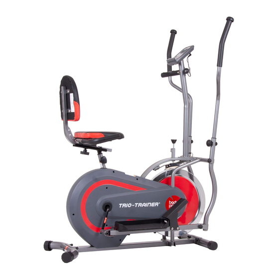
- Page 1 BRT5128 BRT5118 U.S. Patent US474925B1 This product is intended for indoor, home use only and is not to be used in a commercial setting. OWNER’S MANUAL...
- Page 2 PLEASE KEEP THESE INSTRUCTIONS FOR FUTURE USE & REFERENCE. DO NOT DISCARD. WARNING: SERIOUS INJURIES AND EVEN DEATH CAN OCCUR IF THE PROPER SAFETY PRECAUTIONS ARE NOT FOLLOWED. The diagram below highlights and reviews many of the important Safety and Warning labels also found on the unit. Please ensure any user of the unit familiarizes themselves with this Safety and Warning guidelines before use.
-
Page 3: General Information
General Information Safety Storage and Use Before you undertake any exercise program, please be sure to Your product is intended for use in clean dry conditions. You consult with your doctor. should avoid storage in excessively cold or damp places as Frequent strenuous exercise should be approved by your this may lead to corrosion and other related problems. -
Page 4: Before Assembly
Before Assembly WARNING 1. Take a few minutes to familiarize yourself with the parts and hardware included with your product. 2. The assembly may require two people. 3. Check the frame for any damage and check any wiring (if present) for rips or tears. If you detect damage, rips, or tears, please contact our Customer Support Team before beginning any assembly. -
Page 5: Part Listing
Part Listing The following parts list describes all of the parts illustrated in the exploded diagram on the following page. PLEASE NOTE: most of these parts are already pre-assembled on your unit. # Description # Description 01 Main Frame 40 Crankshaft 02 Seat Post 41 Bolt (M8x50 mm) 03 Rear Stabilizer... -
Page 6: Exploded View
Exploded View The following diagram is provided to help you familiarize yourself with the parts and hardware that will be used during the assembly process. : : Not all of the parts and hardware you see here will be used while you are assembling the machine PLEASE NOTE because some of these items are already pre-installed. -
Page 7: Hardware And Tool List
Hardware and Tool List The following hardware is used to assemble your unit. Please take a moment to familiarize yourself with these items. PLEASE NOTE: Most of these parts are already pre-assembled on your unit. Do not be alarmed if you see parts on this page that are not included in your hardware packet. -
Page 8: Assembly Step
Assembly STEP 1 REAR STABILIZER ASSEMBLY Hardware Required Remove the Carriage Bolts (#23), Arc Washers (#31) and Cap Nuts (#28) that are pre-assembled on the Front Stabilizer (#04) and Rear Stabilizer (#03), set them aside as they will be used in a later process. With the help of an assistant, attach the Rear Stabilizer Carriage Bolt (M10x57mm) Arc Washer... - Page 9 Assembly STEP 2 Remove the Nylon Nuts (#27) and Washers (#33) and Wavy Hardware Required Washers (#59) that are pre-assembled on the Handlebar Axle (#20) and set them aside as they will be used later in this step. Insert the Handlebar Axle (#20) through the main frame. Make sure the Handlebar Axle (#20) is centered.
- Page 10 Assembly STEP 3 Hardware Required Right Pedal Hinge Bolt Left Pedal Hinge Bolt [1 piece] [1 piece] Hex Bolt (M10x55 mm) Nylon Nut (M10) Spring Washer [2 pieces] [2 pieces] (1/2") [2 pieces] Left Nylon Nut Right Nylon Nut (w/ black inner nylon ring) (w/ white inner nylon ring) [1 piece] [1 piece]...
- Page 11 Assembly STEP 4 On the right side, attach Right Pedal (#06R) to the Right Hardware Required Pedal Tube (#39) and secure them together using two Hex Bolts (#22) and two Nylon Nuts (#27). Next, attach one Foot Pedal (#07) to the front of Right Pedal Tube (#39) using two Bolts (#41) and secure with four Hex Bolt (M10x45 mm) Bolt (M8x50 mm)
- Page 12 Assembly STEP 5 A. CENTER POST Hardware Required Remove the Bolts (#44) that are pre-assembled on the Main Frame (#01) and set them aside as they will be used in later in this step. Attach the Center Post (#12) to the Main Frame (#01) and Carriage Bolt (M8x73mm) Bolt (M8x30 mm) secure them together by inserting two Bolts (#44) through...
- Page 13 Assembly STEP 6 Remove Knob Bolt (#37) that is pre-assembled on the Hardware Required Main Frame (#01) and set it aside as it will be used in a later process. Select the desired height and secure the Seat Post (#02) to the Main Frame (#01) using one Knob bolt (#37).
-
Page 14: Computer Operation
Computer Operation Key Function MODE : Press this button to select the display function of your SCAN SPEED CALORIES TIME DISTANCE PULSE choice. RESET : Hold MODE button for 3 seconds to reset all value to zero. Operation Procedures FUNCTIONS SCAN : The monitor will then rotate displaying through the following functions: time,speed,distance, calories and odometer. - Page 15 Computer Operation How To Install and Replace Batteries 1. Open the battery door on the back of the computer. 2. The computer operates on two AAA batteries (included). Refer to the illustration to install or replace the batteries. NOTE : 1.
-
Page 16: Safety And Maintenance
Safety and Maintenance Safety & Warning • Make sure all nuts, bolts, and screws are tightened prior to use. • Be sure that all adjustment locking devices and safety devices are properly engaged prior to use! • Never over-tighten the above-mentioned devices and parts to avoid damage to the unit. •... -
Page 17: Troubleshooting
Troubleshooting (AFTER COMPLETE ASSEMBLY) Troubleshoot Area Solution Calories/Distance/ If the computer is not displaying the CALORIES/DISTANCE/TIME/(ETC.) functions (or you are getting inaccurate readings), please adjust Time (Etc.) the following: 1. Check to ensure all computer sensor wires are properly connected and are not damaged. 2. - Page 18 Warm-Up Instructions Before use, you must read and understand all instructions & warnings stated in this Owner’s Manual as well as posted on the equipment. Before beginning any exercise program including the following flexibility exercises, please consult with your physician. The following flexibility exercises are provided to you as a means to prevent injury while you are exercising.
- Page 19 Warm-Up Instructions Shoulder Stretch Quadriceps Stretch Calf Twister 1. Bring your right hand over your 1. Stand on your left leg and hold 1. Place both hands against a wall right shoulder to the onto a support with your left to aid your balance.
- Page 20 THANK YOU FOR YOUR PURCHASE MODEL NO.: BRT5128 BRT5118 Please fill in the information below and keep this manual along with your sales receipt as proof of purchase. Serial Number : Date of Purchase : Retailer : Hupa International, Inc. 21717 Ferrero Parkway Walnut, CA 91789 Phone : 1 (888) 266-6789...
Need help?
Do you have a question about the Trio-Trainer BRT5128 and is the answer not in the manual?
Questions and answers
How to order parts