
Related Manuals for Ametek Land LMG AR

Summary of Contents for Ametek Land LMG AR
- Page 1 LMG AR Signal Processor User Guide Issue 4 29 November 2016 Publication Nº 198.235 Language: English Copyright © 2003-2016 Land Instruments International...
- Page 2 IMPORTANT INFORMATION - PLEASE READ Health and Safety Information Read all of the instructions in this booklet - including all the WARNINGS and CAUTIONS - before using this product. If there is any instruction which you do not understand, DO NOT USE THE PRODUCT.
- Page 3 Web: www.landinst.com For further details on all AMETEK Land offices, distributors and representatives, please visit our websites. Return of Damaged Goods IMPORTANT If any item has been damaged in transit, this should be reported to the carrier and to the supplier immediately.
-
Page 4: Table Of Contents
Contents Introduction 1.1 About this Guide 1.2 About the Processor 1.3 Specifications 1.4 Unpacking the Processor Installing the Processor 2.1 Installing the Processor into a Panel 2.2 Electrical Connections 2.3 System 4 Thermometer Cable Connector Assembly 2.4 AST and AST/4 Thermometer Cable Connector Assembly 2.5 a.c. -
Page 5: Introduction
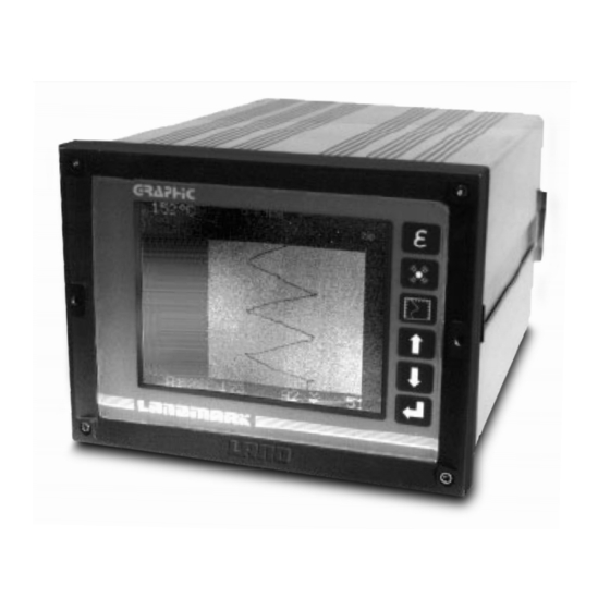
Landmark Graphic AR processor. Basic information regarding installation of the processor is also contained in the Installation Guide. More detailed information regarding servicing, repair and calibration of the processor is contained in the Service Manual. Fig.1 - Landmark Graphic AR Signal Processor 234001 LMG AR Page 1... -
Page 6: About The Processor
The processor’s capabilities can be enhanced with several optional extras. • Serial communications in either RS 232C or RS 485 format. • Maths function option etc. • A front panel cover which provides sealing up to IP65 standards. LMG AR Page 2... -
Page 7: Specifications
Track and Hold: 5 to 24V d.c. or switch/relay contacts Control signal: 10ms Response time: Alarms: High or low, setable 1° steps, setable Trip level: 50V a.c. or d.c. at 0.5A Relay contact rating: 10ms Update: 3° Hysteresis: LMG AR Page 3... - Page 8 Discrimination: 0.003% of FSR Stability: 0.004% of span/° Input Update: 7.5ms Output Update: 30ms NOTE The following functions are not available when utilising the AST Input Cards: 1. mV/° output 2. Peak picking 3. Valley picking LMG AR Page 4...
-
Page 9: Unpacking The Processor
* One of these connectors is supplied for each thermometer channel fitted to the processor. If you have ordered any optional serial communications boards, these will be supplied pre-fitted. Check that you have been supplied with all ordered items. LMG AR Page 5... -
Page 10: Installing The Processor
Fig. 2. Processor front bezel 192mm/7.6in Cut-Out 186 (+1.1,-0)mm /7.3 (+.04,-0)in Protection cover 206mm/8.1in Mounting panel Approximately 400mm/15.8in required for card removal 16mm /0.6in Maximum panel thickness = 13mm/0.5in Fig. 2 - Processor installation dimensions 234002 LMG AR Page 6... - Page 11 Carefully cut a rectangular area out of the panel 186mm/7.3in wide, by 138mm/5.4in high. Refer to Fig. 3. Unscrew the four retaining screws on the rear of the processor and slide out the two clamp bars. From the viewing side, insert the processor in the mounting panel. LMG AR Page 7...
- Page 12 Insert and tighten the retaining screws until the mounting panel is firmly gripped between the processor front panel and the clamp bar. CAUTION Do not overtighten the screws as this will deform the clamp bar. LMG AR Page 8...
-
Page 13: Electrical Connections
Fig. 4 shows the location of the connectors. WARNING Risk of electric shock. Refer to the processor Service Manual before removing the rear panel screws. Ensure that the a.c. mains input is disconnected before removing the rear panel of the processor. LMG AR Page 9... - Page 14 (* Channels B,C & D may not Thermometer connector be identical to A, dependent on RS 485 serial comms output types of thermometers to be Supply voltage selector switch connected) Fig. 4 - Rear panel electrical connections 235004 LMG AR Page 10...
- Page 15 The command input can be controlled via a remote switch, as shown in Fig.7, or via potential-free contacts, as shown in Fig. 8. CMD (Command) input Pin Nº Function Description CMD+ Command input drive CMD- Command input return Fig. 6 - ‘CMD’ (command) cable connection schedule 234006 LMG AR Page 11...
- Page 16 System 4 Card All Cards System 4 Card NOTE Potential-free contacts can be replaced by voltage Vin. Where: >+3.0V = Open Circuit <+1.5V = Closed Circuit Fig. 8 - ‘CMD’ (command) input control via potential-free contacts 234008 LMG AR Page 12...
- Page 17 Current output return resistance: 500Ω Screen Screen Voltage output drive Minimum load Voltage output return resistance: 10kΩ (Not available on AST or I/O cards) Fig. 9a - System 4 thermometer retransmission output cable connection schedule 235009 LMG AR Page 13...
- Page 18 Fig. 9b - AST and AST/4 thermometer retransmission output cable connection schedule 234049 RS 485 200 - 240V 100 - 120V RS 232C 35VA MAX. T 1A 250V 50-60Hz Fig. 10 - Location of screws on back panel 235010 LMG AR Page 14...
- Page 19 User Guide Signal Processor CON 1 D5 D6 Fig. 11 - Location of up scale/down scale selector on the input/output (I/O) p.c.b. S4970077 LMG AR Page 15...
- Page 20 0 to 1100°C 30 to 2000°F 0 to 1600°C 30 to 3200°F Thermometer output Pin Nº Cable Colour Function Yellow Blue White Screen Screen Black Green Fig. 12 - System 4 thermometer cable connection schedule 234012 LMG AR Page 16...
- Page 21 SIGNAL 3 and SIGNAL 4 are not used for AST and AST/4 thermometers. 2.2.5 Serial communications and maths function options For details of any options for the Landmark Graphic AR Processor (e.g. maths function/serial comms), refer to the User Guides supplied with the particular option. LMG AR Page 17...
-
Page 22: System 4 Thermometer Cable Connector Assembly
Refer to Fig. 14. Clip together the two halves of the connector shell ensuring that the ‘write on’ label is held in place by the shell assembly. The connector is now ready for use. LMG AR Page 18... -
Page 23: Ast And Ast/4 Thermometer Cable Connector Assembly
Wire up the connector, remembering the correct orientation of the plug, in accordance with the relevant cable schedule (see Section 2.2). Refer to Fig. 14a. NOTE Keep wire length as short as possible. The connector is now ready for use. LMG AR Page 19... - Page 24 Signal Processor User Guide Keep wire length as short as possible Fig. 14a - Correct AST and AST/4 Thermometer cable connector wiring arrangement 234014a LMG AR Page 20...
-
Page 25: Power Input Plug
IEC connection. The plug complies with BS 4491 - EN60 320. The wiring schedule of the plug assembly is shown in Fig.15. Earth Live Neutral Fig. 15 - a.c. power input plug wiring schedule 234015 LMG AR Page 21... -
Page 26: Using The Processor
Fig. 17 and 18 respectively. Front display panel Cursor ‘up’ key Emissivity adjustment ‘quick key’ Cursor ‘down’ key Alarm adjustment ‘quick key’ ‘Enter’ key Display selector ‘quick key’ Fig. 16 - Front panel display and controls 235049 LMG AR Page 22... - Page 27 User Guide Signal Processor LMG AR Page 23...
- Page 28 Signal Processor User Guide LMG AR Page 24...
-
Page 29: Getting Started (Accessing The Menu System)
The processor display will now be similar to that shown in Fig. 20. A ‘Help’ bar is displayed below each menu, explaining the function of the (UP), (DOWN) and (ENTER) keys for that specific menu. Fig. 19 Typical front panel display 235019 LMG AR Page 25... - Page 30 Signal Processor User Guide Fig. 20 - Access code display 235020 LMG AR Page 26...
- Page 31 Fig. 21 shows the Main Configuration Menu for a processor connected to four thermometers and fitted with a serial communications card. Your system may differ from this (dependant upon the number of channels/options fitted). Fig. 21 - Main configuration menu 234021 LMG AR Page 27...
- Page 32 To select an item to configure, use the UP and DOWN keys to move cursor to the required item. Press the ENTER key. The Configuration Menu for the item you selected from the Main Configuration Menu will now be displayed. Fig. 22 shows the Channel A Configuration Menu for a standard System 4 Thermometer.
-
Page 33: About The Menu System
3.2 About the Menu System Each Configuration Menu comprises the components shown in Fig. 23. The function of each component of the menu is as follows. Main Menu This shows the items that can be altered in the Configuration Menu. Sub Menu This shows the list of options available for each main item in the Configuration Menu. - Page 34 Signal Processor User Guide Main menu Active title bar (white background) Cursor Note area (shows available options) Sub-menu Help Bar Inactive title bar (blue background) Fig. 23 - General Configuration Menu components 234023 LMG AR Page 30...
-
Page 35: Configuring Items In The Menu System
Main Menu. If there is more than one item that can be changed in the sub-menu, pressing the ENTER key reverts the cursor back to a next to the most recently changed item. LMG AR Page 31... - Page 36 CHANGES or the DISCARD CHANGES option and press the ENTER key. The display now reverts to the Main Configuration Menu. To exit the Main Configuration Menu, use the UP and DOWN keys to move cursor to the QUIT option and press the ENTER key. LMG AR Page 32...
-
Page 37: Configuring Constants For Ast And Ast/4 Thermometers
ENTER key. Position the cursor onto the Constants option and press the ENTER key. The display changes to either ‘Calibrate Mode’ (Fig. 25) or ‘Measure Mode’ (Fig. 26), depending upon which mode the unit is configured in. LMG AR Page 33... - Page 38 Signal Processor User Guide Fig. 25 - AST or AST/4 Constants ‘Calibrate Mode’ 234025 Fig. 26 - AST or AST/4 Constants ‘Measure Mode’ 234026 LMG AR Page 34...
- Page 39 PC, the Land-supplied software actually calculates the optimised constants A (H4) and B (H5) and uploads them to the LMG AR. Constants C (H6) and D (H7) are thermometer-specific constants. The values required to be manually input by the user for constants C (H6) and D (H7) differ for every thermometer and may be found on the ‘Type’...
-
Page 40: Using The Quick Keys
Fig. 26 - Emissivity menu 234029 NOTE Channels containing AST I/O cards cannot have their emissivity values adjusted. The emissivity display instead provides an indication of the calculated effective emissivity which has previously been referred to as ‘signal strength’. LMG AR Page 36... - Page 41 User Guide Signal Processor 3.5.2 Alarm Quick key Pressing the key opens up the alarm menu (see Fig. 27). Fig. 27 - Alarms menu 235030 LMG AR Page 37...
- Page 42 This feature is useful in preventing inadvertent or mischevous altering of system settings. The quick key locks are accessed via the main configuration menu. Fig. 28 - Display menu 235031 LMG AR Page 38...
-
Page 43: Time Function Processing
Peak Sample This function allows the unit to peak pick for a user-defined period before the output/display are updated. (Interval 10 to 250 seconds in 1 second steps). For typical Peak Sample responses, see Fig. 30. LMG AR Page 39... - Page 44 Time Fig. 29 - Graphical representation of Peak Picker time function 234032 Processor output Thermometer signal ‘ON’ delay Bottom temp. limit Time Sample time (adjustable) Fig. 30 - Typical output of Peak Sample function 234033 LMG AR Page 40...
-
Page 45: Track And Hold
Closure of potential-free contacts, s/c = Hold TTL level (0 to 5V ) +5V = Track or 0 to 24V +24V = Track 0V = Hold Fig. 31 - Graphical representation of Track and Hold time function 234034 LMG AR Page 41... -
Page 46: Averager
‘trend’ of the input signal rather than rapid changes. Fast averager response speed Slow averager response speed Time Fig. 32 - Graphical representation of Averager time function 234035 LMG AR Page 42... -
Page 47: Valley Picker (Not Available On Ast Or Ast/4 Channels)
234036 Valley Sample: This function allows the unit to Valley pick for a user-defined period before the output/display are updated. (Interval 10 to 250 seconds in 1second steps). For typical Valley Sample responses, see Fig. 34. LMG AR Page 43... - Page 48 Signal Processor User Guide IRT max Valley Sample Output Threshold Temperature Signal Time (adjustable interval 10-250 seconds) Fig. 34 - Typical output of Valley Sample function 234036a LMG AR Page 44...
-
Page 49: Language Selection
The language selector switch, on the rear of the front panel assembly, is now revealed. See Fig. 35. Fig. 35 - Location of language selection switch 234037 LMG AR Page 45... - Page 50 Insert, and tighten, the six screws in the back panel of the processor. Refer to Fig. 10. Language Selection English English English German English English Italian English English French English English Spanish English Japanese English Fig. 36 - Language selector options 234038 LMG AR Page 46...
-
Page 51: Maintenance
User Guide Signal Processor Maintenance The Landmark Graphic AR Signal Processor is designed to be virtually maintenance free. The recommended maximum period between calibration checks is 12 months. LMG AR Page 47... - Page 52 Signal Processor User Guide LMG AR Page 48...
-
Page 53: Appendix A - Display Modes
User Guide Signal Processor Appendix A - Display Modes This section contains typical samples of the displays available from the processor. Fig. A1 - Typical numeric display 234039 Fig. A2 - Typical mixed display 235040 LMG AR Page 49... - Page 54 Signal Processor User Guide Fig. A3 - Typical line chart display 235041 Fig. A4 - Typical deviation chart display 235042 LMG AR Page 50...
- Page 55 User Guide Signal Processor Fig. A5 - Typical 4-channel numeric display 235043 Fig. A6 - Typical 4-channel bar graph display 235044 LMG AR Page 51...
- Page 56 Signal Processor User Guide Fig. A7 - Typical 4-channel deviation bar graph display 235045 Fig. A8 - Typical over-range display 235046 LMG AR Page 52...
- Page 57 User Guide Signal Processor Fig. A9 - Typical under-range display 235047 Fig. A10 - Typical obscuration display 234048 LMG AR Page 53...
- Page 58 Signal Processor User Guide LMG AR...
- Page 59 PRODUCT WARRANTY Thank you for purchasing your new product from Land Instruments International. This Land manufacturer’s ‘back-to-base’ warranty covers product malfunctions arising from defects in design or manufacture. The warranty period commences on the instrument despatch date from the Land Instruments International Ltd.
- Page 60 PRODUCT WARRANTY EXCLUSIONS FROM WARRANTY It should be noted that costs associated with calibration checks which may be requested during the warranty period are not covered within the warranty. Land reserve the right to charge for service/calibration checks undertaken during the warranty period if the cause is deemed to fall outside the terms of the warranty.
Need help?
Do you have a question about the LMG AR and is the answer not in the manual?
Questions and answers