Table of Contents
Advertisement
Quick Links
Operator's Manual
Manual del Usuario
12V/6V, 275A Battery Charger &
Engine Starter
Cargador de batería 12V / 6V, 275A
Motor de arranque
Model/Modelo WC-275
Temperature Controlled
CAUTION:
Read and follow all safety
rules and operating instructions
before every use of this product.
SAVE THESE INSTRUCTIONS.
ATENCIÓN:
Lea y siga todas las reglasde
seguridad e instrucciones de uso
antes de cada uso de este producto.
GUARDE ESTAS INSTRUCCIONES.
Advertisement
Table of Contents

Related Manuals for Smartech WC-275


Summary of Contents for Smartech WC-275
- Page 1 Operator’s Manual Manual del Usuario 12V/6V, 275A Battery Charger & Engine Starter Cargador de batería 12V / 6V, 275A Motor de arranque Model/Modelo WC-275 Temperature Controlled CAUTION: ATENCIÓN: Read and follow all safety Lea y siga todas las reglasde seguridad e instrucciones de uso rules and operating instructions antes de cada uso de este producto.
-
Page 2: Important Safety Instructions
IMPORTANT SAFETY INSTRUCTIONS WARNING! Read and understand all Important Safety and Operating instructions before using this charger. In addition, read and follow all battery and vehicle manufacturer’s instructions and cautionary markings. SAFETY PRECAUTIONS FOR WORKING IN THE VICINITY OF A BATTERY 1. - Page 3 10. This product is NOT intended to supply power to an extra-low-voltage electrical system or to charge dry-cell batteries. Charging dry-cell batteries may burst and cause injury to persons and property. 11. NEVER charge a frozen, damaged, leaking or non-rechargeable battery. 12.
-
Page 4: Grounding And Ac Power Cord Connections
10. Any repair must be carried out by the manufacturer or an authorized repair agent in order to avoid danger. WARNING: This Product contains chemicals including SCCP, PAHs, DBP, DEHP, BBP, DBP, DIBP which are known to the State of California to cause cancer, birth defects or other reproductive harm. - Page 5 Wire size must be large enough for the AC ampere rating of charger, as specified below: Length of cord (feet) AWG* size of cord *AWG-American Wire Gauge How to install the handle? Please follow the instructions. When you take the charger out from the package, the handle is uninstalled. To install the handle, first remove the clamp storage panel by pulling up- wards on it, then use a thin, durable tool (i.e.
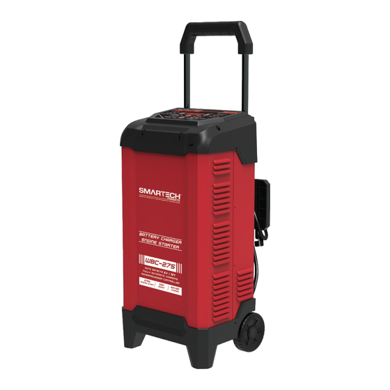
- Page 6 FEATURES WBC-275 USER’S MANUAL PAGE 6...
- Page 7 1. DISPLAY BUTTON 15. BATTERY TYPE BUTTON 2. Voltage LED indicator 16. Digital display 3. Battery % LED indicator 17. ENGINE START BUTTON 4. Alternator % LED indicator 18. Handle 5. CHARGED/MAINTAINING LED 19. Function display panel indicator 6. CHARGING LED indicator 20.
- Page 8 1. This product is designed for charging all types of 6V lead-acid and 12V lead-acid batteries, including WET (Flooded), MF (Maintenance-Free), EFB (Enhanced Flooded Battery), GEL, AGM (Absorbed Glass Mat) batteries. 2. Built-in intelligent microprocessor makes charging faster, easier and safer.
-
Page 9: Display Messages
DISPLAY MESSAGES Startup – Display screen and all LEDs illuminate for 0.5 second. “SMARTECH” text will scroll across the display twice followed by “NO CONNECT” text (if nothing is connected to the charger). TESTING is shown on digital screen, battery voltage shows (meanwhile battery VOLTAGE LED is lit). -
Page 10: Display Button
DISPLAY BUTTON Digital display LED indicator Description When the charger is NOT charging a battery, the display will show the battery VOLTAGE (Voltage value / Alternator% value / OFF in turn by Battery-voltage Voltage LED lit pressing DISPLAY button). When charging BATT-06V or BATT-12V is shown by pressing DISPLAY button. - Page 11 BATTERY TYPE BUTTON Digital display LED indicator Description Charging 6V and 12V WET/MF/EFB 6V / 12V CHARGING batteries. During charging, pressing STD LED lit BATTERY TYPE button is void. Charging 6V and 12V AGM batteries. 6V / 121V During charging, pressing BATTERY CHARGING AGM LED lit TYPE button is void.
-
Page 12: Engine Start Button
60<>30A BOOST (press RATE SELECTION button twice to enter based on OFF mode) – This setting can be used for a quick boost, prior to using the engine start setting. When Boost mode ends, VOLTAGE LED will illuminate and display screen will show battery voltage, and meanwhile BOOST LED will flash. - Page 13 Output current reduces to 0 when temperature in charger is too high. (exceeds 269.6˚/132˚). After cooling down for a few minutes, the charger OVER-TEMP will automatically begin charging with 6<>2A CHARGE/MAINTAIN rate if a battery is connected, and the battery type has memory function and is the same as before.
-
Page 14: Connecting To The Battery
80 RC 12 h 140 RC 18 h MARINE/DEEP-CYCLE 160 RC 20 h 180 RC 22 h Times are based on a 50% discharged battery and may change, depending on age and condition of battery. CONNECTING TO THE BATTERY Identify polarity of battery posts. The positive battery terminal is typi- cally marked by these letters or symbol (POS, P, +). -
Page 15: Operating Steps
OPERATING STEPS Step no. Determine whether or Step select key not to connect Step 1 Correctly connect the charger to the battery BATTERY 6V/12V STD TYPE Step 2 Ensure battery Confirm battery type 6V/12V GEL connection 6V/12V AGM 12V 275A 12V AGM 12V 275A Step 3... -
Page 16: Charging Steps
CHARGING STEPS During the 6V battery type charging process, the charger performs the following operations. STEP 1 – IDENTIFY VOLTAGE Determines if the connected battery is 6V or 12V STEP 2 – CONSTANT CURRENT CHARGE Charges the battery with constant current STEP 3 –... - Page 17 During the 12V battery type charging process, the charger performs the following operations. STEP 1 – IDENTIFY VOLTAGE Determines if the connected battery is 6V or 12V STEP 2 – MULTI CYCLICAL CHARGE Charges the battery with two kinds of cyclical constant current STEP 3 –...
- Page 18 With the charger unplugged from the AC outlet, connect the charger to the battery following the instructions given in the CONNECTING TO THE BATTERY section. Plug the charger AC power cord into the AC outlet. With the charger plugged in and connected to the battery and chassis, press the ENGINE START button until the ENGINE START LED is lit.
-
Page 19: Alternator Check
Cool Down - After cranking, the charger enters a mandatory 240 seconds cool down state (Pressing any button does NOT work). The digital display indicates the remaining cool down time in seconds. It starts at 240 and counts down to 0. After 4 minutes, the digital display will change from displaying the countdown to displaying RDY. -
Page 20: Troubleshooting
Start the vehicle and turn on the vehicle’s headlights. Plug the charger AC power cord into the AC outlet. Read the voltage on the digital display. If you get a reading between 13.2 volts and 14.6 volts, the alternator is working properly. If the reading is less than 13.2 volts or more than 14.6 volts, have the charging system checked by a qualified technician. - Page 21 This warranty gives you specific legal rights, and you may also have other rights which vary from state to state. Product distributed in the United States by Smartech Inc. 8700 Larkin Rd. Suite B Savage, MD 20763 www.SmartechProduct.com...
- Page 22 WBC-275 USER’S MANUAL PAGE 22...
Need help?
Do you have a question about the WC-275 and is the answer not in the manual?
Questions and answers