Table of Contents
Advertisement
Advertisement
Chapters
Table of Contents

Related Manuals for Honda EZ6500CXS


Summary of Contents for Honda EZ6500CXS
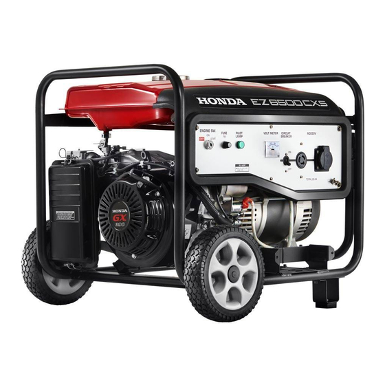
- Page 1 GENERATOR OWNER’S MANUAL EZ6500CXS...
- Page 2 Please be advised that unit was designed / manufactured for specific applications. So please do not modify and use the unit for any application other than which it was designed for. If you have any questions regarding any applications, please ask Honda dealer before using.
-
Page 3: Table Of Contents
Table of Contents 1. SAFETY LABEL LOCATION ..........3 2. IMPORTANT SAFETY INFORMATION ....... 5 3. COMPONENTS ..............7 4. CONTROLS ................. 11 5. BEFORE STARTING ENGINE ..........14 6. OPERATION ................ 15 7. STOPPING ENGINE ............18 8. MAINTENANCE ..............19 9. -
Page 4: Safety Label Location
1.SAFETY LABEL LOCATION These labels warn you of potential hazards that can cause serious injury. Read them carefully. If a label comes off or becomes hard to read, contact your Honda dealer for a replacement. EXHAUST CONNECT CAUTION CAUTION READ OWNER’S... - Page 5 ・ Honda generator is designed to give safe and dependable service if operated according to instructions. Read and understand the Owner’s Manual before operating the generator. Failure to do so could result in personal injury or equipment damage. ・ Exhaust contains poisonous carbon monoxide, a colorless, odorless gas.
-
Page 6: Important Safety Information
– Do not operate the generator with any cover removed. You may get your hand or foot caught in the generator and it may cause accident. – Consult your authorized Honda dealer for disassembly and service of the generator that are not covered in this manual. - Page 7 Electric Shock Hazards The generator produces enough electric power to cause a serious shock or electrocution if misused. • Do not use in wet conditions. Keep the generator dry. – Do not use in the rain or snow. – Do not use near a pool or a sprinkler system. –...
-
Page 8: Components
3.COMPONENTS CHOKE CONTROL PANEL CLEANER BATTERY (A battery is not in at the time of the FUEL factory shipment.) VALVE OIL FILLER CAP STATER GRIP OIL DRAIN PLUG FUEL TANK CAP FUEL GAUGE FUEL TANK SPARK PLUG MUFFLER... - Page 9 Type : R VOLT METER CIRCUIT BREAKER PILOT LAMP FUSE SWITCH FUSE AC OUTPUT GROUND TERMINAL Type : REH VOLT METER CIRCUIT BREAKER PILOT LAMP FUSE SWITCH FUSE AC OUTPUT GROUND TERMINAL...
- Page 10 Type : RK VOLT METER CIRCUIT BREAKER PILOT LAMP FUSE SWITCH FUSE AC OUTPUT GROUND TERMINAL Type : M VOLT METER CIRCUIT BREAKER PILOT LAMP FUSE SWITCH FUSE AC OUTPUT GROUND TERMINAL...
- Page 11 Type : S VOLT METER CIRCUIT BREAKER PILOT LAMP FUSE SWITCH FUSE AC OUTPUT GROUND TERMINAL...
-
Page 12: Controls
4. CONTROLS Engine switch To start and stop the engine. Switch position: ON:To run the engine after starting. OFF:To stop the engine. START:To start the engine by turning the starter motor. START Return the key to the “ON” position once the engine has started. Do not use the starter for more than 5 seconds at a time. - Page 13 Fuel valve The fuel valve is located between the fuel tank and carburetor. When the valve lever is in the “ON” position, fuel is allowed to flow from the fuel tank to the carburetor. Be sure to return the lever to “OFF” after stopping the engine. ON Position OFF Position Choke Rod...
- Page 14 Circuit Breaker The Circuit breaker will automatically cut off the circuit if there is a short circuit or a significant overload of the generator at the receptacle. If the circuit breaker is OFF automatically, check that the appliance is working properly and does not exceed the rated load capacity of the circuit before ON position to push the circuit breaker.
-
Page 15: Before Starting Engine
5. BEFORE STARTING ENGINE Be sure to check the generator on a level surface with the engine stopped. Before each use, look around and underneath the engine for signs of oil or gasoline leaks. 1. Fill recommended engine oil to the upper level if the oil is short. 2. -
Page 16: Operation
6.OPERATION STARTING THE ENGINE Manual start (Use the Recoil starter) Make sure that all electrical loads from panel receptacles are disconnected. The generator may be hard to start if a load is connected. Turn the fuel valve to the “ON” position. If you want to start operating the choke manually, move the choke rod to the OPEN... - Page 17 Do not allow the starter grip to snap back against the engine. Return it gently to prevent damage to the starter or housing. If you have manually closed the choke, move it to the “OPEN” position as the engine warms up. Electric start Take steps (1) through (3) in “MANUAL START”...
- Page 18 2. APPLYING AC LOAD Start engine (see STARTING THE ENGINE). Allow the engine to warm up for 2-3 minutes before connecting tools or appliances. Insert the plug of the electrical appliance into “AC RECEPTACLE”. ** Do not take a current exceeding the specified amperage. ** Be sure that total wattage of all appliances does not exceed the rated output of the generator.
-
Page 19: Stopping Engine
7. STOPPING ENGINE Disconnect all electrical loads from panel receptacles. Turn the engine switch to the “OFF” position. Turn the fuel valve to the “OFF” position. Never leave an appliance plugged into the generator when you stop the generator as damage could result to the generator and / or appliance. -
Page 20: Maintenance
8. MAINTENANCE Periodic inspection and adjustment of Honda engine & Generator is essential if high-level performance is to be maintained. Regular maintenance will also ensure a long service life. The required service intervals and kind of maintenance to be performed are described on OWNER’S MANUAL. - Page 21 Engine oil Engine oil is a major factor affecting engine performance and service life. Non detergent oils and 2-stroke engine oils will damage the engine and are not recommended. Check the oil level BEFORE EACH USE with the generator on a level surface with the engine stopped.
- Page 22 Used motor oil may cause skin cancer if repeatedly left in contact with the skin for prolonged periods. Although this is unlikely unless you handle used oil on a daily basis, it is still advisable to thoroughly wash your hands with soap and water as soon as possible after handling used oil.
-
Page 23: Plug
UPPER LIMIT MARK (RED) LEVEL GAUGE Spark plug service Recommended spark plugs: EZ6500CXS: W16EPR-U (DENSO), BPR5ES (NGK) To ensure proper engine operation, the spark plug must be properly gapped and free of deposits. If the engine has been running, the muffler will be very hot. Be careful not to touch the muffler. -
Page 24: Washer
The gap should be: 0.7mm-0.8mm 0.7mm-0.8mm Check that the spark plug washer is in good condition, and thread the spark plug in by hand to prevent cross-threading. After the spark plug is seated, tighten with a spark plug wrench to compress the washer. -
Page 25: Cover
Unsnap the air cleaner cover clips, remove CLIP AIR CLEANER COVER the air cleaner cover, and remove the element. Wash the element in a solution of household detergent and warm water, then rinse thoroughly; or wash in nonflammable or high flash point solvent. Allow the element to dry thoroughly. -
Page 26: Transporting And Storage
9. TRANSPORTING AND STORAGE When transporting the generator, turn the engine switch and the fuel valve “OFF”. Keep the generator level to prevent fuel spillage. Fuel vapor or spilled fuel may ignite. Touch a hot engine or exhaust system can cause serious burns or fires. Let the engine cool before transporting or storing the generator. - Page 27 1) Drain the carburetor by loosening the drain screw. Drain the gasoline into a suitable container. Gasoline is extremely flammable and is explosive under certain conditions. Perform this task in a well ventilated area with the engine stopped. Do not smoke or allow flames or sparks in the area during this procedure.
-
Page 28: Wattage Information
The following wattage chart is guidance only. Refer to your specific appliance for correct wattage. APPLICABLE WATTAGE (W) EZ6500CXS MODEL APPLIANCE 50Hz 60Hz... -
Page 29: Trouble Shooting
11. TROUBLE SHOOTING When the engine will not start: Is there fuel in the Refill the fuel tank. tank? Is there enough oil in Add the recommended the engine? oil. Take the generator to Is there a spark from Replace the an authorized your the spark plug? spark plug. - Page 30 Starter motor does not turn round: Is the battery Is the starter motor still does discharged? not turn round, take the generator to your dealer. Charge the battery. ***If your generator still fails to start or generate electricit y, contact Honda dealer.
-
Page 31: Specification
12. SPECIFICATION MODEL EZ6500CXS ★ENGINE Model Honda GX390 Displacement Oil alert system Starting System Recoil & Electric Oil Capacity ℓ ★GENERATOR System Self-exciting, 2pole, field rotating type Voltage regulation system Phase Single Rated power factor cosφ Insulation Class TYPE Rated Voltage... -
Page 32: Wiring Diagram
13. WIRING DIAGRAM Type : R, S... - Page 33 Type : REH...
- Page 34 Type : RK...
- Page 35 Type : M...
-
Page 36: Appendix
APPENDIX 1. LOOSE PARTS 2. INSTALLATION OF BATTERY 3. INSTALLATION OF WHEEL KIT... - Page 37 1. LOOSE PARTS Check all loose parts against the following list. Contact your dealer if any of the loose parts shown below are not included with your generator. Type : R, S Ref. No. Description Qty. PLUG PLUG WRENCH SHAFT WHEEL WASHER COVER...
-
Page 38: Flange Bolt M8-16
Type : REH Ref. No. Description Qty. PLUG PLUG WRENCH SHAFT WHEEL WASHER COVER FLANGE BOLT M8-16 FLANGE NUT M8 STAND SNAP PIN PLATE , BATTERY FLANGE BOLT M6-12 OWNER’S MANUAL ④ ③ ② ① ⑥ ⑦ ⑤ ⑨ ⑩ ⑧... - Page 39 Type : RK Ref. No. Description Qty. PLUG PLUG WRENCH SHAFT WHEEL WASHER COVER FLANGE BOLT M8-16 FLANGE NUT M8 STAND SNAP PIN PLATE , BATTERY FLANGE BOLT M6-12 OWNER’S MANUAL ④ ③ ② ① ⑦ ⑥ ⑤ ⑩ ⑪ ⑨...
- Page 40 Type : M Ref. No. Description Qty. PLUG PLUG WRENCH SHAFT WHEEL WASHER COVER FLANGE BOLT M8-16 FLANGE NUT M8 STAND SNAP PIN PLATE , BATTERY FLANGE BOLT M6-12 OWNER’S MANUAL ④ ③ ① ② ⑦ ⑥ ⑤ ⑩ ⑪ ⑨...
- Page 41 2. INSTALLATION OF BATTERY Batteries produce explosive gases: If ignited, and explosion can cause serious injury or blindness. Provide adequate ventilation when charging. CHEMICAL HAZARD: battery electrolyte contains sulfuric acid. Contact with eyes or skins, even through clothing, may cause severe burns. Wear a face shield and protective clothing.
- Page 42 5. Install the battery. Install battery plate using two M6-12mm flange bolts. TORQUE : 8.0 – 12.0 N・ ・ ・ ・ m REMOVAL Remove the battery plate. 2. Remove the negative (-) cable from the battery negative (-) terminal, and then remove the positive (+) cable from the battery.
-
Page 43: Flange Bolt M6-12
3. INSTALLATION OF WHEEL KIT 1. Install the two stands on the under frame using M8-16mm flange bolts and M8 nuts. TORQUE : 20.0 – 24.0 N・ ・ ・ ・ m 2. Install wheels on the side of frame bracket with shaft and cover. 3. - Page 44 EZ6500CXS ’ OWNER S MANUAL 42Y168001...
Need help?
Do you have a question about the EZ6500CXS and is the answer not in the manual?
Questions and answers