Table of Contents
Advertisement
INSTALLATION MANUAL
AIR CONDITIONER
• Please read this installation manual completely before installing the product.
• Installation work must be performed in accordance with the national wiring
standards by authorized personnel only.
• Please retain this installation manual for future reference after reading it thoroughly.
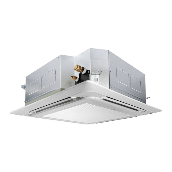
TYPE : CEILING CASSETTE
Model : LT-H282PLE0, LT-H332NLE0, LT-H452MLE0
LT-H512MLE0, LT-C282PLE0, LT-C332NLE0
LT-C452MLE0, LT-C512MLE0, LT-C48BMLE0
LT-C52BMLE0
P/NO : MFL42291417
www.lg.com
Advertisement
Table of Contents

Subscribe to Our Youtube Channel
Related Manuals for LG LT-H282PLE0


Summary of Contents for LG LT-H282PLE0
- Page 1 • Installation work must be performed in accordance with the national wiring standards by authorized personnel only. • Please retain this installation manual for future reference after reading it thoroughly. TYPE : CEILING CASSETTE Model : LT-H282PLE0, LT-H332NLE0, LT-H452MLE0 LT-H512MLE0, LT-C282PLE0, LT-C332NLE0 LT-C452MLE0, LT-C512MLE0, LT-C48BMLE0 LT-C52BMLE0 www.lg.com...
- Page 2 TIPS FOR SAVING ENERGY TIPS FOR SAVING ENERGY Here are some tips that will help you minimize the power consumption when you use the air conditioner. You can use your air conditioner more efficiently by referring to the instructions below: •...
- Page 3 SAFETY PRECAUTIONS IMPORTANT SAFETY INSTRUCTIONS READ ALL INSTRUCTIONS BEFORE USING THE APPLIANCE. Always comply with the following precautions to avoid dangerous situations and ensure peak performance of your product WARNING It can result in serious injury or death when the directions are ignored CAUTION It can result in minor injury or product damage when the directions are ignored WARNING...
- Page 4 SAFETY PRECAUTIONS • Do not install the product on a defective installation stand. - It may cause injury, accident, or damage to the product. • Be sure the installation area does not deteriorate with age. - If the base collapses, the air conditioner could fall with it, causing property damage, product failure, and personal injury.
-
Page 5: Table Of Contents
TABLE OF CONTENTS TABLE OF CONTENTS INTRODUCTION Fea tures INSTALLATION Installation Tools Installation of Indoor, Outdoor Unit Remote Control Preparation Wiring Connection Connecting Pipes to the Indoor Unit Installation of Decorative Panel Indoor Unit Drain Piping Air Purging Test running Installation guide at the seaside... -
Page 6: Introduction
INSTALLATION PARTS INTRODUCTION Features Filter Air Outlet Air Inlet Remote Controller... -
Page 7: Installation
INSTALLATION INSTALLATION Installation Tools Figure Name Figure Name Screw driver Ohmmeter Electric drill Hexagonal wrench Measuring tape, Knife Ammeter Hole core drill Gas-leak detector Thermometer, Spanner Horizontal meter Torque wrench Flaring tool set Manifold gauges Vacuum pump... -
Page 8: Installation Of Indoor, Outdoor Unit
INSTALLATION Installation of Indoor, Outdoor Outdoor unit - If an awning is built over the unit to prevent Unit direct sunlight or rain exposure, be careful that heat radiation from the condenser is not Selection of the best location restricted. Indoor unit - There should not be any animals or plants which could be affected by hot air dis-... - Page 9 *Additional mm(inch) Model refrigerant (g/m) Liquid Standard Max. Standard Max. LT-H282PLE0 15.88(5/8”) 6.35(1/4”) LT-H332NLE0 15.88(5/8”) 6.35(1/4”) LT-H452MLE0 19.05(3/4”) 9.52(3/8”) LT-H512MLE0 19.05(3/4”) 9.52(3/8”) LT-C282PLE0 15.88(5/8") 6.35(1/4") LT-C332NLE0 15.88(5/8") 6.35(1/4") LT-C452MLE0 19.05(3/4") 9.52(3/8") LT-C512MLE0 19.05(3/4") 9.52(3/8") LT-C48BMLE0 19.05(3/4”) 9.52(3/8”) LT-C52BMLE0 19.05(3/4”) 9.52(3/8”)
- Page 10 INSTALLATION Ceiling opening dimensions and hanging bolt location - The dimensions of the paper model for installing are the same as those of the ceiling opening dimensions. - Select and mark the position for fixing bolts and piping hole. - Decide the position for fixing bolts slightly tilted to the drain direction after considering the direction of drain hose.
- Page 11 INSTALLATION NOTE Thoroughly study the following installation locations: In such places as restaurants and kitchens, considerable amount of oil steam and flour adhere to the turbo fan, the fin of the heat exchanger and the drain pump, resulting in heat exchange reduction, spraying, dispersing of water drops, drain pump malfunction, etc.
- Page 12 INSTALLATION The Indoor Unit Installation Ceiling Keep the length of the bolt Hanging bolt from the bracket to 40mm (W3/8 or M10) Flat washer for M10 Air Conditioner body (W3/8 or M10) (accessory) Ceiling board Ceiling board Spring washer (M10) Keep the length of 15~18mm between the air conditioner bottom surface and the ceiling surface...
-
Page 13: Remote Control Preparation
INSTALLATION Remote Control Preparation HOW TO MOUNT ONTO A WALL HOW TO INSERT BATTERIES Remove the battery cover from the remote - Do not use rechargeable bat- controller. teries, such batteries differ - Slide the cover according to the arrow from standard dry cells in direction. -
Page 14: Wiring Connection
Cable 1 Phase Terminal Block of Outdoor Unit Terminal Block of Indoor Unit 1(L) 2(N) 1 (L) 2(N) 3 1(L) 2(N) LT-H282PLE0 Heatpump Model POWER INPUT Terminal Block of Indoor Unit 1 Phase 1(L) 2(N) 1 (L) 2(N) 3 1(L) - Page 15 (Rubber insulation, type H05RN-F approved by HAR or SAA). Attach insulation sleeve Round crimp-style terminal Electricwire Normal Model Cross-Sectional LT-H282PLE0 3.5mm (3 wires) LT-H332NLE0 5.5mm (3 wires) LT-H452MLE0 6.5mm (3 wires) LT-H512MLE0 LT-C282PLE0 3.5mm...
- Page 16 Holder for power supply cord / LOCAL REGULATION. connecting cable Power supply cord Over 5mm Cover control Main power Model Circuit Breaker (A) source LT-H282PLE0 LT-H332NLE0 Circuit Breaker Use circuit breaker or time delay fuse. LT-H452MLE0 Switch box LT-H512MLE0 LT-C282PLE0 LT-C332NLE0 LT-C452MLE0...
-
Page 17: Connecting Pipes To The Indoor Unit
INSTALLATION Connecting Pipes to the Indoor Unit Putting nut on - Remove flare nuts attached to indoor and - Preparation of Piping outdoor units, than put them on pipe/tube Main cause of gas leakage is defect in flaring having completed burr removal. work. - Page 18 INSTALLATION Check Liquid side *Compare the flared work with figure below. *If flare is noted to be defective, cut off the Indoor flared section and do flaring work again. unit - If the piping and the drain hose are in com- Outdoor mon direction bundle the piping and the drain Flare connection...
-
Page 19: Installation Of Decorative Panel
INSTALLATION Installation of Decorative Panel Insert two screws on diagonal corners of panel. Do not tighten the bolts completely. (The fixing screws are included in the The decorative panel has its installation indoor unit box.) direction. Check the alignment of panel with the ceil- Before installing the decorative panel, ing. - Page 20 INSTALLATION Open two screws of control panel cover. Fit the link on the panel as shown in pic- ture. (The link is included in the front panel unit box.) Link Screw Connect one display connector and two vane control connectors of front panel to indoor unit PCB.
-
Page 21: Indoor Unit Drain Piping
INSTALLATION Indoor Unit Drain Piping CAUTION - Drain piping must have down-slope (1/50 to Install certainly the decorative panel. 1/100): be sure not to provide up-and-down Cool air leakage causes sweating. ⇨ slope to prevent reversal flow. Water drops fall. - During drain piping connection, be careful not to exert extra force on the drain port on the indoor unit. - Page 22 INSTALLATION Drain test HEAT INSULATION The air conditioner uses a drain pump to drain - Use the heat insulation material for the water. refrigerant piping which has an excellent heat-resistance (over 120°C). Use the following procedure to test the drain pump operation: - Precautions in high humidity circumstance: This air conditioner has been tested accord-...
- Page 23 INSTALLATION Form the pipings In case of the Outdoor Unit being Wrap the connecting portion of indoor unit installed above position of the Indoor with the Insulation material and secure it Unit. with two Plastic Bands. (for the right pip- ings) •...
-
Page 24: Air Purging
INSTALLATION Air Purging CAUTION Air purging Be sure to use a manifold valve for air The air and moisture remaining in the refriger- purging. If it is not available, use a stop ant system have undesirable effects as indi- valve for this purpose. The "Hi" knob of cated below. - Page 25 INSTALLATION Soap water method Indoor unit - Remove the caps from the 3-way(#1) and 3- way(#2) valves. - Remove the service-port cap from the 3- way(#2) valve. - To open the 3-way(#1) valve turn the valve stem counterclockwise approximately 90°, wait for about 2~3 sec, and close it.
-
Page 26: Test Running
INSTALLATION - Once the desired vacuum is created. CHECK THE FOLLOWING ITEMS WHEN Disconnect the vacuum pump and open the INSTALLATION IS COMPLETED liquid side valve stem by turning it to count- - After completing work, be sure to measure er-clockwise direction with service valve and record trial run properties, and store wrench. - Page 27 INSTALLATION Evaluation of the performance CAUTION - Measure the temperature of the intake and discharge air. • Confirm that the cable thickness is as specified in the power sources specifi- - Ensure the difference between the intake cation. temperature and the discharge one is more (Particularly note the relation between than 8°C (Cooling) or reversely (Heating).
-
Page 28: Installation Guide At The Seaside
Install the outdoor unit on - If you can’t meet above guide line in the the opposite side of the sea wind direction. seaside installation, please contact LG Electronics for the additional anticorro- sion. - Periodic ( more than once/year ) cleaning...
Need help?
Do you have a question about the LT-H282PLE0 and is the answer not in the manual?
Questions and answers