Table of Contents
Advertisement
Advertisement
Table of Contents

Related Manuals for Asus ROG STRIX B550-A GAMING


Summary of Contents for Asus ROG STRIX B550-A GAMING
- Page 1 ROG STRIX B550-A GAMING...
- Page 2 Product warranty or service will not be extended if: (1) the product is repaired, modified or altered, unless such repair, modification of alteration is authorized in writing by ASUS; or (2) the serial number of the product is defaced or missing.
-
Page 3: Table Of Contents
Contents Safety information ...................... iv About this guide ......................v ROG STRIX B550-A GAMING specifications summary .......... vi Connectors with shared bandwidth ................x Package contents ....................... xi Installation tools and components ................xii Chapter 1: Product Introduction Before you proceed ................... 1-1 Motherboard layout .................. -
Page 4: Safety Information
Safety information Electrical safety • To prevent electrical shock hazard, disconnect the power cable from the electrical outlet before relocating the system. • When adding or removing devices to or from the system, ensure that the power cables for the devices are unplugged before the signal cables are connected. If possible, disconnect all power cables from the existing system before you add a device. -
Page 5: About This Guide
Refer to the following sources for additional information and for product and software updates. ASUS website The ASUS website (www.asus.com) provides updated information on ASUS hardware and software products. Optional documentation Your product package may include optional documentation, such as warranty flyers, that may have been added by your dealer. -
Page 6: Rog Strix B550-A Gaming Specifications Summary
2400/2133 MHz, Un-buffered Memory* Memory Dual Channel Memory Architecture OptiMem II * ECC memory (ECC mode) support varies by CPU. * Refer to www.asus.com for the Memory QVL (Qualified Vendors Lists). 1 x DisplayPort 1.2* Graphics 1 x HDMI 2.1 (4K@60HZ) * Graphics specifications may vary between CPU types. - Page 7 ROG STRIX B550-A GAMING specifications summary ROG SupremeFX 7.1 Surround Sound High Definition Audio CODEC S1220A - Impedance sense for front and rear headphone outputs - Jack-detection, Multi-streaming, Front Panel Jack-retasking - High quality 120 dB SNR stereo playback output and 113 dB SNR...
- Page 8 AURA Sync - Aura RGB headers - Addressable Gen 2 RGB header ASUS Q-Design - ASUS Q-DIMM - ASUS Q-LED (DRAM [yellow],CPU [red], VGA [white], Boot Device [yellow green]) - ASUS Q-Slot ASUS Thermal Solution Special Features - Aluminum M.2 heatsink design ASUS EZ DIY - BIOS Flashback™...
- Page 9 Manageability Windows 10 64 - bit Operating System ATX Form Factor Form Factor 12 inch x 9.6 inch (30.5 cm x 24.4 cm) Specifications are subject to change without notice. Please refer to the ASUS website for the latest specifications.
-
Page 10: Connectors With Shared Bandwidth
Connectors with shared bandwidth FLBK_LED1 RGB_HEADER1 CPU_FAN CPU_OPT BIOS_FLBK EATX12V_2 EATX12V_1 U2_56U32G1_78 DIGI+ U32G2_C6 U32G2_5 BOOT LAN_U32G1_34 DRAM HDMI AUDIO Intel ® I225-V 256Mb BIOS 2280 2260 2242 22110 PCIEX16_1 B550 Super BATTERY PCIEX1_1 PCIEX16_2 PCIEX1_2 AURA 22110 2280 2260 2242 PCIEX1_3 COM_DEBUG... -
Page 11: Package Contents
Package contents Check your motherboard package for the following items. Motherboard 1 x ROG STRIX B550-A GAMING motherboard 1 x Addressable RGB extension cable Cables 4 x SATA 6Gb/s cables 1 x Cable ties pack 1 x M.2 Rubber Package 1 x M.2 SSD screw package... -
Page 12: Installation Tools And Components
Installation tools and components Phillips (cross) screwdriver PC chassis Power supply unit AMD AM4 CPU AMD AM4/AM3 compatible CPU Fan DDR4 DIMM SATA hard disk drive SATA optical disc drive (optional) Graphics card (optional) M.2 SSD module (optional) 1 Bag of screws The tools and components in the table above are not included in the motherboard package. -
Page 13: Chapter 1: Product Introduction
Before you install or remove any component, ensure that the ATX power supply is switched off or the power cord is detached from the power supply. Failure to do so may cause severe damage to the motherboard, peripherals, or components. ROG STRIX B550-A GAMING... -
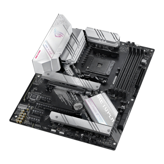
Page 14: Motherboard Layout
Motherboard layout 24.4cm(9.6in) FLBK_LED1 RGB_HEADER1 CPU_FAN CPU_OPT BIOS_FLBK EATX12V_2 EATX12V_1 U2_56U32G1_78 DIGI+ U32G2_C6 BOOT LAN_U32G1_34 DRAM HDMI AUDIO Intel ® I225-V 256Mb BIOS 2280 2260 2242 22110 PCIEX16_1 B550 Super BATTERY PCIEX1_1 PCIEX16_2 PCIEX1_2 AURA 22110 2280 2260 2242 PCIEX1_3 COM_DEBUG USB_E34 USB_E12 PANEL... - Page 15 11. AURA RGB headers 1-16 12. Clear CMOS header 1-17 13. Front Panel Audio header 1-18 14. System Panel header 1-19 15. Thermal sensor header 1-20 16. Thunderbolt header 1-20 17. BIOS FlashBack™ LED 1-21 18. Q-LED 1-21 ROG STRIX B550-A GAMING...
- Page 16 CPU socket The motherboard comes with an AMD Socket AM4 designed for 3 Gen AMD Ryzen™ Processors. SOCKET AM4 The AM4 socket has a different pinout design. Ensure that you use a CPU designed for the AM4 socket. The CPU fits in only one correct orientation. DO NOT force the CPU into the socket to prevent bending the connectors on the socket and damaging the CPU! Ensure that all power cables are unplugged before installing the CPU.
- Page 17 (Double Data Rate 4) memory modules. A DDR4 memory module is notched differently from a DDR, DDR2, or DDR3 module. DO NOT install a DDR, DDR2, or DDR3 memory module to the DDR4 slot. Recommended memory configurations ROG STRIX B550-A GAMING...
- Page 18 (D/C) from the same vendor. Check with the vendor to get the correct memory modules. • Visit the ASUS website for the latest QVL. Chapter 1: Product Introduction...
- Page 19 We recommend that you provide sufficient power when running CrossFireX™ mode. • Ensure to connect the 8-pin and 4-pin power plugs when running CrossFireX™ mode. • Connect a chassis fan to the chassis fan connectors when using multiple graphics cards for better thermal environment. ROG STRIX B550-A GAMING...
- Page 20 Hyper M.2 X16 series card configuration Slot PCIe bifurcation settings in PCIe x16 slots with different Ryzen™ CPUs Gen AMD Ryzen™ Processors (Support PCIe Gen 4 SSDs) Supported SSDs PCIEX16_1 • Hyper M.2 X16 series card is purchased separately. • When using 3 Gen AMD Ryzen™...
- Page 21 For water cooling kits, connect the pump connector to the AIO_PUMP header. Header Max. Current Max. Power Default Speed Shared Control CPU_FAN Q-Fan Controlled CPU_OPT Q-Fan Controlled CHA_FAN1 Q-Fan Controlled CHA_FAN2 Q-Fan Controlled CHA_FAN3 Q-Fan Controlled AIO_PUMP Full-Speed ROG STRIX B550-A GAMING...
- Page 22 Power connectors These Power connectors allow you to connect your motherboard to a power supply. The power supply plugs are designed to fit in only one orientation. Find the proper orientation and push down firmly until the power supply plugs are fully inserted. EATX12V_2 EATX12V_1 PIN 1...
- Page 23 M.2_2 slot supports PCIe 3.0 x4 and SATA modes Key M design and type 2242/2260/2280/ 22110 storage devices. • When M.2_2 slot is populated, SATA6G_5/6 will be disabled. The M.2 SSD module is purchased separately. ROG STRIX B550-A GAMING 1-11...
- Page 24 RAID set using these connectors, set the SATA Mode Selection item in the BIOS to [RAID]. • Before creating a RAID set, refer to the RAID Configuration Guide. You can download the RAID Configuration Guide from the ASUS website. • When M.2_2 slot is populated, SATA6G_5/6 ports will be disabled. Chapter 1: Product Introduction...
- Page 25 USB 3.2 Gen 1 ports. The USB 3.2 Gen 1 header provides data transfer speeds of up to 5 Gb/s. U32G1_12 PIN 1 USB3+5V USB3+5V IntA_P1_SSRX- IntA_P2_SSRX- IntA_P1_SSRX+ IntA_P2_SSRX+ IntA_P1_SSTX- IntA_P2_SSTX- IntA_P1_SSTX+ IntA_P2_SSTX+ IntA_P1_D- IntA_P2_D- IntA_P1_D+ IntA_P2_D+ The USB 3.2 Gen 1 module is purchased separately. ROG STRIX B550-A GAMING 1-13...
- Page 26 USB 2.0 headers The USB 2.0 headers allow you to connect USB modules for additional USB 2.0 ports. The USB 2.0 headers provide data transfer speeds of up to 480 Mb/s. USB_E34 USB_E12 PIN 1 DO NOT connect a 1394 cable to the USB connectors. Doing so will damage the motherboard! The USB 2.0 module is purchased separately.
- Page 27 5V connector is aligned with the 5V header on the motherboard. • The addressable RGB LED strip will only light up when the system is powered on. • The addressable RGB LED strip is purchased separately. ROG STRIX B550-A GAMING 1-15...
- Page 28 AURA RGB headers The RGB headers allow you to connect RGB LED strips. RGB_HEADER1 PIN 1 +12V G R B RGB_HEADER2 PIN 1 +12V G R B The RGB headers support 5050 RGB multi-color LED strips (12V/G/R/B), with a maximum power rating of 3A (12V).
- Page 29 If the steps above do not help, remove the onboard battery and short the two pins again to clear the CMOS RTC RAM data. After clearing the CMOS, reinstall the battery. ROG STRIX B550-A GAMING 1-17...
- Page 30 Front Panel Audio header The front panel audio header is for a chassis-mounted front panel audio I/O module that supports HD Audio. Connect one end of the front panel audio I/O module cable to this header. We recommend that you connect a high-definition front panel audio module to this connector to avail of the motherboard’s high-definition audio capability.
- Page 31 Pressing the power switch for more than four seconds while the system is ON turns the system OFF. • Reset button (2-pin RESET) This 2-pin header is for the chassis-mounted reset button for system reboot without turning off the system power. ROG STRIX B550-A GAMING 1-19...
- Page 32 Thermal Sensor header The Thermal Sensor header allows you to connect a sensor to monitor the temperature of the devices and the critical components inside the motherboard. Connect the thermal sensor and place it on the device or the motherboard’s component to detect its temperature.
- Page 33 BOOT (YELLOW GREEN) VGA (WHITE) CPU (RED) DRAM (YELLOW) The Q-LEDs provide the most probable cause of an error code as a starting point for troubleshooting. The actual cause may vary from case to case. ROG STRIX B550-A GAMING 1-21...
- Page 34 Chapter 1: Product Introduction 1-22...
-
Page 35: Building Your Pc System
NOT force the CPU into the socket to prevent bending the connectors on the socket and damaging the CPU! • ASUS will not cover damages resulting from incorrect CPU installation/removal, incorrect CPU orientation/placement, or other damages resulting from negligence by the user. -
Page 36: Cooling System Installation
2.1.2 Cooling system installation Apply the Thermal Interface Material to the CPU heatsink and CPU before you install the heatsink and fan if necessary. CPU Heatsink and fan assembly Type 1 Chapter 2: Basic Installation... - Page 37 CPU Heatsink and fan assembly Type 2 When using this type of CPU fan, remove the screws and the retention module only. Do not remove the plate on the bottom. ROG STRIX B550-A GAMING...
- Page 38 To install an AIO cooler If you wish to install an AIO cooler, we recommend installing the AIO cooler after installing the motherboard into the chassis. AIO_PUMP CPU_FAN CPU_OPT Chapter 2: Basic Installation...
-
Page 39: Dimm Installation
2.1.3 DIMM installation To remove a DIMM ROG STRIX B550-A GAMING... -
Page 40: Installation
2.1.4 M.2 installation • The M.2 rubber pad is optional for when installing a single sided M.2 storage device. Ensure to install the bundled M.2 rubber pad before installing your single sided M.2 storage device. OPTIONAL • DO NOT install the bundled M.2 rubber pads when installing a double-sided M.2 storage device. - Page 41 The M.2 is purchased separately. ROG STRIX B550-A GAMING...
-
Page 42: Motherboard Installation
2.1.5 Motherboard installation Place the motherboard into the chassis, ensuring that its rear I/O ports are aligned to the chassis’ rear I/O panel. Place nine (9) screws into the holes indicated by circles to secure the motherboard to the chassis. DO NOT over tighten the screws! Doing so can damage the motherboard. -
Page 43: Atx Power Connection
ATX power connection • DO NOT connect the 4-pin power plug only, the motherboard may overheat under heavy usage. • Ensure to connect the 8-pin power plug, or connect both the 8-pin and 4-pin power plugs. ROG STRIX B550-A GAMING... -
Page 44: Sata Device Connection
2.1.7 SATA device connection Chapter 2: Basic Installation 2-10... -
Page 45: Front I/O Connector
AAFP To install USB 3.2 Gen 1 connector To install USB 2.0 connector USB 3.2 Gen 1 USB 2.0 This connector will only fit in one orientation. Push the connector until it clicks into place. ROG STRIX B550-A GAMING 2-11... -
Page 46: Expansion Card Installation
2.1.9 Expansion card installation To install PCIe x16 cards To install PCIe x1 cards Chapter 2: Basic Installation 2-12... -
Page 47: Bios Update Utility
• Updating BIOS may have risks. If the BIOS program is damaged during the process and results to the system’s failure to boot up, please contact your local ASUS Service Center. ROG STRIX B550-A GAMING... -
Page 48: Motherboard Rear And Audio Connections
Motherboard rear and audio connections 2.3.1 Rear I/O connection Rear panel connectors USB 2.0 ports 5 and 6 USB 3.2 Gen 2 Type-A port 5 Intel I225-V 2.5Gb Ethernet port* ® DisplayPort BIOS FlashBack™ button USB 3.2 Gen 1 Type-A ports 7 and 8 USB 3.2 Gen 2 Type-C port C6 ®... - Page 49 Front Speaker Out Front Speaker Out Front Speaker Out Pink Mic In Mic In Mic In Mic In Orange – – Center/Sub woofer Center/Sub woofer Black – Rear Speaker Out Rear Speaker Out Rear Speaker Out ROG STRIX B550-A GAMING 2-15...
-
Page 50: Audio I/O Connections
2.3.2 Audio I/O connections Audio I/O ports Connect to Headphone and Mic Connect to Stereo Speakers Connect to 2-channel Speakers Chapter 2: Basic Installation 2-16... - Page 51 Connect to 4-channel Speakers Connect to 5.1-channel Speakers Connect to 7.1-channel Speakers ROG STRIX B550-A GAMING 2-17...
-
Page 52: Starting Up For The First Time
Starting up for the first time After making all the connections, replace the system case cover. Ensure that all switches are off. Connect the power cord to the power connector at the back of the system chassis. Connect the power cord to a power outlet that is equipped with a surge protector. Turn on the devices in the following order: Monitor External storage devices (starting with the last device on the chain) -
Page 53: Chapter 3: Bios And Raid Support
Knowing BIOS The new ASUS UEFI BIOS is a Unified Extensible Interface that complies with UEFI architecture, offering a user-friendly interface that goes beyond the traditional keyboard- only BIOS controls to enable a more flexible and convenient mouse input. You can easily navigate the new UEFI BIOS with the same smoothness as your operating system. -
Page 54: Bios Setup Program
BIOS setup program Use the BIOS Setup to update the BIOS or configure its parameters. The BIOS screen includes navigation keys and brief onscreen help to guide you in using the BIOS Setup program. Entering BIOS at startup To enter BIOS Setup at startup, press <Delete> or <F2> during the Power-On Self Test (POST). -
Page 55: Asus Ez Flash 3
ASUS EZ Flash 3 The ASUS EZ Flash 3 feature allows you to update the BIOS without using an OS-based utility. Ensure to load the BIOS default settings to ensure system compatibility and stability. Select the Load Optimized Defaults item under the Exit menu or press hotkey <F5>. -
Page 56: Asus Crashfree Bios 3
The BIOS file in the motherboard support DVD may be older than the BIOS file published on the ASUS official website. If you want to use the newer BIOS file, download the file at https://www.asus.com/support/ and save it to a USB flash drive. -
Page 57: Raid Configurations
For more information on configuring your RAID sets, please refer to the RAID Configuration Guide which you can find at https://www.asus.com/support, or by scanning the QR code. RAID definitions RAID 0 (Data striping) optimizes two identical hard disk drives to read and write data in parallel, interleaved stacks. - Page 58 Chapter 3: BIOS and RAID Support...
-
Page 59: Appendix
Appendix Notices FCC Compliance Information Responsible Party: Asus Computer International Address: 48720 Kato Rd., Fremont, CA 94538, USA Phone / Fax No: (510)739-3777 / (510)608-4555 This device complies with part 15 of the FCC Rules. Operation is subject to the following two conditions: (1) This device may not cause harmful interference, and (2) this device must accept any interference received, including interference that may cause undesired operation. - Page 60 Compliance Statement of Innovation, Science and Economic Development Canada (ISED) This device complies with Innovation, Science and Economic Development Canada licence exempt RSS standard(s). Operation is subject to the following two conditions: (1) this device may not cause interference, and (2) this device must accept any interference, including interference that may cause undesired operation of the device.
- Page 61 ASUS products sold in Vietnam, on or after September 23, 2011,meet the requirements of the Vietnam Circular 30/2011/TT-BCT. Các sản phẩm ASUS bán tại Việt Nam, vào ngày 23 tháng 9 năm2011 trở về sau, đều phải đáp ứng các yêu cầu của Thông tư 30/2011/TT-BCT của Việt Nam.
- Page 62 ASUS Recycling/Takeback Services ASUS recycling and takeback programs come from our commitment to the highest standards for protecting our environment. We believe in providing solutions for you to be able to responsibly recycle our products, batteries, other components as well as the packaging materials.
- Page 63 Директив. Повний текст декларації відповідності стандартам ЄС доступний s bitnim zahtjevima i ostalim odgovarajućim odredbama vezanih direktiva. на: www.asus.com/support Cijeli tekst EU izjave o sukladnosti dostupan je na: www.asus.com/support Türkçe AsusTek Computer Inc., bu aygıtın temel gereksinimlerle ve ilişkili Čeština Společnost ASUSTeK Computer Inc. tímto prohlašuje, že Yönergelerin diğer ilgili koşullarıyla uyumlu olduğunu beyan eder.
-
Page 64: Asus Contact Information
+1-510-739-3777 +1-510-608-4555 Web site https://www.asus.com/us/ Technical Support Support fax +1-812-284-0883 Telephone +1-812-282-2787 Online support https://qr.asus.com/techserv ASUS COMPUTER GmbH (Germany and Austria) Address Harkortstrasse 21-23, 40880 Ratingen, Germany Web site https://www.asus.com/de Online contact https://www.asus.com/support/Product/ContactUs/ Services/questionform/?lang=de-de Technical Support Telephone (DE) +49-2102-5789557 Telephone (AT)
Need help?
Do you have a question about the ROG STRIX B550-A GAMING and is the answer not in the manual?
Questions and answers