Table of Contents
Advertisement
Quick Links
OPERATOR'S MANUAL
REPRODUCTION OF THIS MANUAL IN ANY FORM WITHOUT WRITTEN APPROVAL OF BAILEIGH INDUSTRIAL
HOLDINGS LLC IS PROHIBITED. Baileigh Industrial Holdings LLC, Inc. does not assume and hereby disclaims any
liability for any damage or loss caused by an omission or error in this Operator's Manual, resulting from accident,
negligence, or other occurrence.
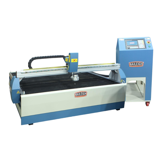
PLASMA CUTTING TABLE
MODEL: PT-44AH-W
Baileigh Industrial Holdings LLC
P.O. Box 531
Manitowoc, WI 54221-0531
Phone: 920.684.4990
Fax: 920.684.3944
sales@baileigh.com
© 2019 Baileigh Industrial Holdings LLC
Rev. 07/2019
Advertisement
Table of Contents

Related Manuals for Baileigh Industrial PT-44AH-W

Summary of Contents for Baileigh Industrial PT-44AH-W
- Page 1 REPRODUCTION OF THIS MANUAL IN ANY FORM WITHOUT WRITTEN APPROVAL OF BAILEIGH INDUSTRIAL HOLDINGS LLC IS PROHIBITED. Baileigh Industrial Holdings LLC, Inc. does not assume and hereby disclaims any liability for any damage or loss caused by an omission or error in this Operator’s Manual, resulting from accident, negligence, or other occurrence.
-
Page 2: Table Of Contents
Plasma Cutting Mode Type ..................37 CUTTING PARAMETER PROCEDURE ............... 38 Cutting Height ......................39 Arc Voltage ........................ 39 LUBRICATION AND MAINTENANCE ................40 ELECTRICAL DIAGRAM ....................41 SOFTWARE INFORMATION ..................42 BobCAD-CAM Contacts: ....................42 PT-44AH-W QUICK REFERENCE GUIDE ..............45... -
Page 3: Thank You & Warranty
THANK YOU & WARRANTY Thank you for your purchase of a machine from Baileigh Industrial Holdings LLC. We hope that you find it productive and useful to you for a long time to come. Inspection & Acceptance. Buyer shall inspect all Goods within ten (10) days after receipt thereof. Buyer’s payment shall constitute final acceptance of the Goods and shall act as a waiver of the Buyer’s rights to inspect or... - Page 4 We apologize for any discrepancies that may occur. Baileigh Industrial Holdings LLC reserves the right to make any and all changes deemed necessary in the course of business including but not limited to pricing, product specifications, quantities, and product availability.
-
Page 5: Introduction
INTRODUCTION The quality and reliability of the components assembled on a Baileigh Industrial Holdings LLC machine guarantee near perfect functioning, free from problems, even under the most demanding working conditions. However, if a situation arises, refer to the manual first. If a solution cannot be found, contact the distributor where you purchased our product. -
Page 6: Safety Instructions
IMPORTANT PLEASE READ THIS OPERATORS MANUAL CAREFULLY It contains important safety information, instructions, and necessary operating procedures. The continual observance of these procedures will help increase your production and extend the life of the equipment. SAFETY INSTRUCTIONS LEARN TO RECOGNIZE SAFETY INFORMATION This is the safety alert symbol. - Page 7 SAVE THESE INSTRUCTIONS. Refer to them often and use them to instruct others. PROTECT EYES Wear safety glasses or suitable eye protection when working on or around machinery. PROTECT AGAINST NOISE Prolonged exposure to loud noise can cause impairment or loss of hearing.
- Page 8 ELECTRICAL AND MAGNETIC FIELDS Electric current used with plasma cutting creates electric and magnetic fields (EMF). These magnetic fields can have an effect on pacemakers and other sensitive electronic equipment. If you wear a pacemaker or similar device contact your doctor before operating this type of equipment.
-
Page 9: Safety Precautions
HIGH VOLTAGE USE CAUTION IN HIGH VOLTAGE AREAS. DO NOT assume the power to be off. FOLLOW PROPER LOCKOUT PROCEDURES. EMERGENCY STOP BUTTON In the event of incorrect operation or dangerous conditions, the machine can be stopped immediately by pressing the E-STOP button. Twist the emergency stop button clockwise (cw) to reset. - Page 10 ! ..P SAFELY! LEASE ENJOY YOUR AILEIGH MACHINE LEASE ENJOY IT 1. FOR YOUR OWN SAFETY, READ INSTRUCTION MANUAL BEFORE OPERATING THE MACHINE. Learn the machine’s application and limitations as well as the specific hazards. 2. Only trained and qualified personnel can operate this machine. 3.
- Page 11 18. DO NOT operate machine if under the influence of alcohol or drugs. Read warning labels on prescriptions. If there is any doubt, DO NOT operate the machine. 19. Sparks and hot material from cutting can easily go through small cracks and openings into adjacent areas.
-
Page 12: Technical Specifications
TECHNICAL SPECIFICATIONS 82.75” x 90" x 40” (2102 x 2286 x 1016mm) Table Dimensions (W x L x H) 59” x 59” (1500 x 1500mm) Cutting Area (X x Y) 3.4” (86mm) Z Axis Travel 19.6” (500mm) Table Working Height 1"... -
Page 13: Unpacking And Checking Contents
UNPACKING AND CHECKING CONTENTS Your Baileigh machine is shipped complete. Separate all parts from the packing material and check each item carefully. Make certain all items are accounted for before discarding any packing material. WARNING: SUFFOCATION HAZARD! Immediately discard any plastic bags and packing materials to eliminate choking and suffocation hazards to children and animals. -
Page 14: Transporting And Lifting
TRANSPORTING AND LIFTING NOTICE: Lifting and carrying operations should be carried out by skilled workers, such as a truck operator, crane operator, etc. If a crane is used to lift the machine, attach the lifting chain carefully, making sure the machine is well balanced. Follow these guidelines when lifting with truck or trolley: •... -
Page 15: Installation
INSTALLATION IMPORTANT: Consider the following when looking for a suitable location to place the machine: • Overall weight of the machine. • Weight of material being processed. • Sizes of material to be processed through the machine. • Space needed for auxiliary stands, work tables, or other machinery. •... -
Page 16: Getting To Know Your Machine
GETTING TO KNOW YOUR MACHINE Item Name Description “Y” axis drive (Y-1) Consists of stepper motor, belt, and gear rack “X” axis cable track Supports and protects cables as carriage travels “X” axis drive Consists of stepper motor, belt, and gear rack “Z”... -
Page 17: Assembly And Set Up
IMPORTANT: Items a and b are included with the plasma cutter. These items are not included if you do not purchase a plasma cutter from Baileigh Industrial. You will need to contact your plasma cutter provider for these components and connection information. -
Page 18: Torch Mounting
Torch Mounting 1. Power the console on and fully lower the Z axis. 2. Power the console off. 3. If installed, remove the gear rack from the torch body by taking out the socket screw, pivoting the rack, and carefully pulling it out from the torch mounting tube. 4. -
Page 19: Torch Cable Routing
Torch Cable Routing The plasma torch cable is typically routed through the cable tracks and cable trays back to the plasma cutter power unit. It is generally common to start at the torch holder and work back to the plasma cutter. 1. - Page 20 4. Allow for a loop (C) from the torch to the entry point (D) of the cable track. This will help to eliminate unnecessary stress on the cable. 5. At the entry end of the cable track, remove the two screws securing the cable track mounting link to the support bracket.
- Page 21 14. Route the torch cable through the Y axis cable track positioning the cable towards the outboard side of the track. 15. When the torch cable is routed through the Y axis cable track, carefully connect the mounting link to the main cable track chain and secure the mounting link to the support bracket.
-
Page 22: Water Fill
Water Fill Add water to the table tank until the water level at the top of the material supports. Drain, clean and refill will be based upon usage. Heavy usage will fill the table with debris while light usage will allow bacteria to grow. Add a general anti-bacterial as needed. -
Page 23: Electrical
ELECTRICAL CAUTION: HAVE ELECTRICAL UTILITIES CONNECTED TO MACHINE BY A CERTIFIED ELECTRICIAN! Check if the available power supply is the same as listed on the machine nameplate. WARNING: Make sure the grounding wire (green) is properly connected to avoid electric shock. DO NOT switch the position of the green grounding wire if any electrical plug wires are switched during hookup. -
Page 24: Cord And Power Connection
• Improper connection of the equipment-grounding conductor can result in risk of electric shock. The conductor with insulation having an outer surface that is green with or without yellow stripes is the equipment-grounding conductor. If repair or replacement of the electric cord or plug is necessary, do not connect the equipment-grounding conductor to a live terminal. -
Page 25: Plasma Cutter Wire Connections
PLASMA CUTTER WIRE CONNECTIONS NOTICE: This system uses 50:1 divided voltage. YOU MUST VERIFY THIS WITH THE PLASMA CUTTER MANUFACTURER. Damage from using the incorrect divided voltage is not covered by warranty. This table requires 6 wire connections to the plasma cutter. -
Page 26: Software
Thermal Dynamics IMPORTANT: THIS IS FOR REFERENCE ONLY. This instruction is based upon generally available information. Contact the manufacturer of your plasma cutter for specific set up information. Signal Sockets / Wire No. Wire Colors Start / Stop (plasma arc) 3, 4 Red, Black OK to Move (start machine motion) -
Page 27: Ohmic Clip Connection
Ohmic Clip Connection IMPORTANT: THE OHMIC CLIP CONNECTION WILL NOT FUNCTION WITH ALL MAKES AND MODELS OF PLASMA CUTTERS! The Ohmic clip circuit allows the torch to sense the material electrically during the touch off function. This provides a more precise torch height position for the pierce and start of the cut. Without the Ohmic clip the torch still senses the material using a physical contact from the torch breakaway circuit. - Page 28 Miller IMPORTANT: THIS IS FOR REFERENCE ONLY. This diagram is based upon generally available information. Contact the manufacturer of your plasma cutter for specific set up information. 3. Prepare the table for a test cut. 4. Observe the IHS Signal indicator. The indicator dot for the IHS Signal should be Red until the torch tip touches the material and turns to Green during touch test.
-
Page 29: Plasma Table Start-Up Procedure
PLASMA TABLE START-UP PROCEDURE • Verify that all cables are connected to the console. • MAKE SURE all equipment is properly grounded. Consult a qualified electrician. • Verify that all components have the correct utilities connected both electrical and air. (Consult individual operator’s manuals) •... -
Page 30: General Plasma Table Information
GENERAL PLASMA TABLE INFORMATION Whether cutting an artful design to be hung on a wall as a decoration or a simple plate to be welded to an I-beam to hold up the wall, plasma cutting like most metal working has an artistic component to completing a successful cut. - Page 31 Table Operation Once an object has been drawn and coded into G code format, it may be taken to the table to have the table run the pattern. This is what the table does. It is all the table does. Run a pattern of the specific object that has been loaded to run.
- Page 32 5.5 (15.2) 1794 Mild Steel @ 60A (mm) Volts (mm) (mm/min) (mm) (sec) (mm) 6.2 (15.2) 5080 As is visible, the Pierce Delay is the same between the two amp settings. All other settings are different. The largest variation is the cutting speed. A setting like Kerf is best planned for and set in the software.
-
Page 33: Basic / Quick Controller Operation
BASIC / QUICK CONTROLLER OPERATION General Commands Note: This is a quick overview. Refer to book two for a more detailed explanation of the controller operation and other more detailed functions. • The basic HOME screen will be similar to what appears above. The [M] line will be “Plasma Cut”;... -
Page 34: General Operation Steps
• The function (“F keys”) are used to operate the system. Access files, change operator setting, and tune operation. • Pressing the “SPACE” key will change the function (“F keys”) to display more cutting options. • When making changes to parameters, be sure to save the change. This is typically the “F8” key. - Page 35 • From the “Home” screen, press F4 to enter the settings pages. In the settings pages, F1 “Common” and F3 “Plasma” are typical screens for operational changes. The other screens are not used or do not normally have settings that should be changed. •...
- Page 36 • The F3 Plasma screen settings are also available from the main screen. The main differenece between the Main screen access to the F3 setting and the F1 is that the F3 settings are changed in steps while the F1 settings open a dialog box which allows for entry of a specific value.
- Page 37 • After Save, press “ESC” to return to the “Home” screen. • Pressing the F3 key will open the Part Options functions. These can be used to change and alter the file which is loaded. F7 Revert will cancel ALL changes applied to the file. PRACTICE THESE CHANGES UNTIL YOU ARE COMFORTABLE WITH THE OUTCOME.
- Page 38 • Pressing the “Space” key will change the function keys to other choices. IMPORTANT: The Demo and Frame functions WILL cause the table/gantry to move. Verify that the head and torch will not contact material or tools and that all persons around the machine are clear and away from the table.
-
Page 39: Plasma Cutting Mode Type
IMPORTANT: This instruction is based upon generally available information at the time of testing. Baileigh Industrial Holdings LLC. Cannot be held accountable for changes made to the plasma cutter which may change these results. Contact the manufacturer of your plasma cutter for specific set up information. -
Page 40: Cutting Parameter Procedure
CUTTING PARAMETER PROCEDURE This is the procedure used to determine the setting use create the best possible cut. 1. Verify that the material is clean and free of oil, paint, and rust. 2. Verify that the ground clamp is clamped directly to the material to be cut. 3. -
Page 41: Cutting Height
Cutting Height An automatic height control system is invaluable when plasma cutting with a mechanical torch. Using it can provide the proper cutting height for various material thicknesses when transferring the arc, piercing, and cutting. Below are some examples of how the torch height can affect the cut. -
Page 42: Lubrication And Maintenance
LUBRICATION AND MAINTENANCE WARNING: Make sure the electrical disconnect is OFF before working on the machine. Maintenance should be performed on a regular basis by qualified personnel. Always follow proper safety precautions when working on or around any machinery. Note: Proper maintenance can increase the life expectancy of your machine. Daily Maintenance •... -
Page 43: Electrical Diagram
ELECTRICAL DIAGRAM... -
Page 44: Software Information
SOFTWARE INFORMATION Each new cutting table comes with one license of the latest version of BobCAD CAM Express software and Services provided by BobCAD-CAM. Contact a representative from BobCAD-CAM to get started with BobCAD-CAM. The service representative will help to get you directed to the download links and the license activated. Whether drawing squares or squirrels, flanges or flowers, BobCAD-CAM will help to bring out your drafting artistry skills. - Page 45 Use the information below to ensure you are working with a BobCAD-CAM supported and optimized system. Use the following link to view the most up to date system requirements. http://bobcad.com/support/system-requirements/?source=webinars_footer BobCAD-CAM is supported to run on the following Operating Systems: •...
- Page 46 NOTES...
-
Page 47: Pt-44Ah-W Quick Reference Guide
PT-44AH-W QUICK REFERENCE GUIDE PT-44AH-W QUICK REFERENCE GUIDE HANGE ETTINGS OAD FILE ➢ FROM Plasma Power Supply Manual Cutting Table. ➢ From Main Menu F2 File Match the materials with the cutting amperage and ➢ F1 DISK FILE (System Storage) the consumables. - Page 48 BAILEIGH INDUSTRIAL HOLDINGS LLC 1625 D , WI 54220 UFEK RIVE ANITOWOC : 920. 684. 4990 F : 920. 684. 3944 HONE www.baileigh.com BAILEIGH INDUSTRIAL HOLDINGS LTD. U WIFT OINT WIFT ALLEY NDUSTRIAL STATE UGBY , CV21 1QH U IDLANDS...