
Related Manuals for CTE B-LIFT 18 HV

Summary of Contents for CTE B-LIFT 18 HV
- Page 1 INSTRUCTIONS FOR USE AND MAINTENANCE MOBILE ELEVATING WORK PLATFORM 18 HV FABRICATION NR......COD UM0287_GB | REV. 00 | ED: 09/18...
- Page 2 It is prohibited to reproduce, store or alteration, even partial, of this publication, without written permission by the CTE SPA. CTE S.P.A. reserves the right to make changes to the lifting platform, for any technical and commercial need, without having to update every time this publication.
-
Page 3: Table Of Contents
........................2.6.5 Ambient air temperature ....................... 2.6.6 Humidity ............................14 2.6.7 Noise level ............................14 2.6.8 Vibrations and crashes ......................... 2.6.9 Gas emissions ..........................15 2.6.10 Contaminant agents ........................B-LIFT 18 HV Aerial work platform COD. UM0287_GB | REV. 00 | ED: 09/18... - Page 4 5.11 Stabilization control device _________________________________________________ 5.12 Control device for driving on the road _________________________________________ 5.13 Dispositivo di controllo area di lavoro _________________________________________ 5.14 Spirit level ______________________________________________________________ B-LIFT 18 HV Aerial work platform COD. UM0287_GB | REV. 00 | ED: 09/18...
- Page 5 ..................8.5.4 Lubricating the turntable ......................... Hydraulic system maintenance ______________________________________________ 8.6.1 Hydraulic cylinders .........................9 8.6.2 Hydraulic system pipes ........................8.6.3 Pressure check and valve adjustment ................... B-LIFT 18 HV Aerial work platform COD. UM0287_GB | REV. 00 | ED: 09/18...
- Page 6 Maintenance checklist ____________________________________________________ 14 Facsimiles of EC Declaration and Certiicates 15 Optional equipment and accessories 15.1 Dead-man-control: pedal in the basket on the work platform _______________________ 15.2 5000V Insulated work platform ______________________________________________ B-LIFT 18 HV Aerial work platform COD. UM0287_GB | REV. 00 | ED: 09/18...
- Page 7 INDEX 15.3 Directable work light ______________________________________________________ 15.4 Auxiliary electric motor ____________________________________________________ 15.5 Automatic stabilization ____________________________________________________ B-LIFT 18 HV Aerial work platform COD. UM0287_GB | REV. 00 | ED: 09/18...
- Page 8 INDEX This page intentionally left blank B-LIFT 18 HV Hubarbeitsbühne COD. UM0287_DE | REV. 00 | ED: 09/18...
-
Page 9: General Information
The manufacturer shall hold themselves exempt from all responsibility and obligations for any damage and/or injury caused by the following: • Use of the machine outside the limits described in this manual. B-LIFT 18 HV Aerial work platform COD. UM0287_GB | REV. 00 | ED: 09/18... -
Page 10: Content And Scope Of This Manual
This symbol is used to highlight operations or procedures that are STRICTLY PROHIBITED. OBLIGATORY Round symbol with blue background and white symbol. WARNING Note on key functions or useful information regarding the operation in progress. 1.3.2 Illustrations B-LIFT 18 HV Aerial work platform COD. UM0287_GB | REV. 00 | ED: 09/18... -
Page 11: Scope Of This Manual
The operator is directly responsible for the machine and its use. This manual does not contain instructions for maintenance operations, which must be performed only by specialised personnel or by CTE SpA authorised service centres. CAUTION Before using the machine, carefully read the manual and be sure you understand all the safety standards and operating instructions. -
Page 12: Intended Readership
O P T I O N A L E Q U I P M E N T A N D lists the optional devices and describes them ACCESSORIES 1.3.6 Intended readership B-LIFT 18 HV Aerial work platform COD. UM0287_GB | REV. 00 | ED: 09/18... -
Page 13: Conservation
The technical information (text, drawings and illustrations) contained in this manual are property of CTE S.p.A. and should be considered conidential. It is strictly prohibited to disclose, reproduce or translate this document, in whole or in part, without written authorisation from CTE S.p.A. B-LIFT 18 HV Aerial work platform... -
Page 14: Glossary
The assembly consisting of the mobile platform and the vehicle (or carriage). A qualiied technician trained for carrying out the maintenance. Service engineer Authorised service Company with one or more qualified technicians authorised by the centre manufacturer to carry out extraordinary maintenance and repairs. B-LIFT 18 HV Aerial work platform COD. UM0287_GB | REV. 00 | ED: 09/18... - Page 15 All devices and systems used to stabilise the mobile elevating work Stabilisers platforms by supporting and/or levelling the entire mobile elevating work platform or extending structure, for example jacks, suspension locking devices etc. B-LIFT 18 HV Aerial work platform COD. UM0287_GB | REV. 00 | ED: 09/18...
- Page 16 Hazardous area Any area inside and/or near a machine where there is a continuous risk for the safety and health of the persons exposed. B-LIFT 18 HV Aerial work platform COD. UM0287_GB | REV. 00 | ED: 09/18...
-
Page 17: Safety
COUNCIL dated 8 May 2000 on the approximation of the laws of the 2000/14/EC 08/05/2000 Member States relating to the noise emission in the environment by equipment for use outdoors. B-LIFT 18 HV Aerial work platform COD. UM0287_GB | REV. 00 | ED: 09/18... -
Page 18: Intended And Improper Use
• maintenance of industrial plant and factories • maintenance of electrical lines and the installation of electrical systems • pruning B-LIFT 18 HV Aerial work platform COD. UM0287_GB | REV. 00 | ED: 09/18... -
Page 19: Non-Permitted Use
Observe the minimum safety distances required by the current national regulations or, in their absence, refer to the minimum distances indicated in the table at the side (ref. ISO 18893: 2014). B-LIFT 18 HV Aerial work platform COD. UM0287_GB | REV. 00 | ED: 09/18... -
Page 20: Tipping Hazard
3° slope. • Exceed the maximum load on the work platform and the maximum number of persons allowed (table of load quantities in the technical speciications and on the machine). B-LIFT 18 HV Aerial work platform COD. UM0287_GB | REV. 00 | ED: 09/18... -
Page 21: Beaufort Wind Scale
Wind felt on face, leaves pronounced. Crests Light breeze rustle, ordinary vanes begin 6-11 have a glassy to move appearance and do not break. B-LIFT 18 HV Aerial work platform COD. UM0287_GB | REV. 00 | ED: 09/18... -
Page 22: Risk Of Falling
Attach safety harness cables to the connection provided on the work platform. • Keep the platform clear of debris. • Check that the access gate to the work platform is properly closed before using the platform. B-LIFT 18 HV Aerial work platform COD. UM0287_GB | REV. 00 | ED: 09/18... -
Page 23: Collision Hazard
The lifting platform and relative electrical equipment MUST NOT be installed on surfaces that transmit vibrations and in environments where there is a danger of impact with other mechanical units. B-LIFT 18 HV Aerial work platform COD. UM0287_GB | REV. 00 | ED: 09/18... -
Page 24: Machine Hazards
Ensure that the manual is intact, legible and kept in the special container in the cab. • The machine is equipped with an internal combustion engine that generates noise, the values of which are show in Chapter 3. B-LIFT 18 HV Aerial work platform COD. UM0287_GB | REV. 00 | ED: 09/18... -
Page 25: Operator Deinition
The operators should be suitably instructed on the use of the lifting platform. It is particularly important that the operator on the ground preventively knows the exact position and use of controls for emergency manoeuvres. B-LIFT 18 HV Aerial work platform COD. UM0287_GB | REV. 00 | ED: 09/18... -
Page 26: Training And Importance Of The Procedures
Supervision of the recording of operations performed in workshops authorised by CTE. B-LIFT 18 HV Aerial work platform COD. UM0287_GB | REV. 00 | ED: 09/18... -
Page 27: Summary Of Operator Standards
Before manoeuvring, always check that there are no obstacles or persons in the way. CAUTION The manufacturer shall bear no liability if the above standards are not complied with. B-LIFT 18 HV Aerial work platform COD. UM0287_GB | REV. 00 | ED: 09/18... -
Page 28: Road Trafic
When operating inside production areas (construction sites and industrial sites) take special care when positioning the vehicle. Wherever possible, choose the operating area (or working envelope) of the lifting platform also according to the following suggestions: B-LIFT 18 HV Aerial work platform COD. UM0287_GB | REV. 00 | ED: 09/18... -
Page 29: Positioning The Machine
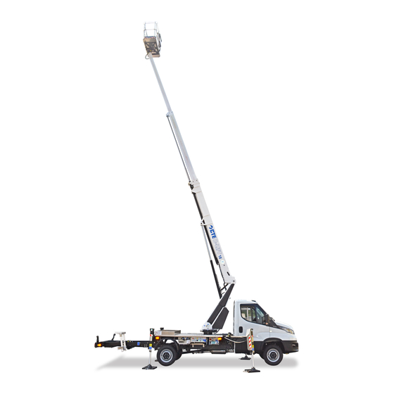
Use appropriate signals for operations on roadworks sites. Fig. Maximum outreach of the aerial work platform (AWP) Maximum working height Diagram is indicative only. For data and all measurements, refer to Chapter 3. B-LIFT 18 HV Aerial work platform COD. UM0287_GB | REV. 00 | ED: 09/18... -
Page 30: Risks For Exposed Persons
2.5 m/sec² • the weighted root mean square acceleration value to which the main body is exposed is less than 0.5 m/sec B-LIFT 18 HV Aerial work platform COD. UM0287_GB | REV. 00 | ED: 09/18... -
Page 31: Gas Emissions
If the operator detects a contaminant agent that could cause the machine to malfunction, s/he must immediately call a CTE assistance centre to verify its suitability for use. 2.6.11 Ionising and non-ionising radiation The electrical equipment DOES NOT have additional protection against radiation (microwaves, ultra violet rays, laser, X-rays). -
Page 32: Personal Protective Equipment (Ppe)
DANGER! It is prohibited to use the anchorage point on the platform to connect fall arrest systems. B-LIFT 18 HV Aerial work platform COD. UM0287_GB | REV. 00 | ED: 09/18... -
Page 33: Additional Personal Protective Equipment
Risk of crushing feet when stabilising the machine. • Risk of crushing limbs by boom joints during the closing process. The areas of risk are indicated with labels (see Chapter 3). B-LIFT 18 HV Aerial work platform COD. UM0287_GB | REV. 00 | ED: 09/18... - Page 34 Chapter 2 SAFETY This page intentionally left blank B-LIFT 18 HV Aerial work platform COD. UM0287_GB | REV. 00 | ED: 09/18...
-
Page 35: Description And Technical Data
Chapter 15. General description of the machine The B-lift 18 HV elevating work platform consists of a frame bolted to the chassis of the vehicle. The upper part of the frame consists of a slip resistant aluminium platform. -
Page 36: Classiication
DESCRIPTION DESCRIPTION Upper Bottom Right-hand side Left-hand side Rear Front The following diagrams illustrate the references and the convention used to identify the machine’s stabilizers. Fig. B-LIFT 18 HV Aerial work platform COD. UM0287_GB | REV. 00 | ED: 09/18... -
Page 37: Identiication And Ce Marking
NON LOADED MASS WITH VEHICLE ° ° ° INCLINAZIONE MASSIMA AMMISSIBILE DEL TELAIO: MAXIMUM ALLOWABLE INCLINATION OF CHASSIS: ALIMENTAZIONE ELETTRICA ESTERNA EXTERNAL ELECTIC POWER CODE Fig. B-LIFT 18 HV Aerial work platform COD. UM0287_GB | REV. 00 | ED: 09/18... -
Page 38: Description Of Main Units
220V outlet Boom lifting cylinder Ground electrical panel Emergency controls distributor Stabilizer control levers Turntable Rear stabilizer Rotation system Telescopic extension Basket support plate Fig. The picture shows one possible coniguration of the machine, which may vary. B-LIFT 18 HV Aerial work platform COD. UM0287_GB | REV. 00 | ED: 09/18... -
Page 39: Main Pictograms
"T". Il differenziale deve scattare. Ripristinare il dispositivo sollevando le leve dell'nterruttore generale. Se ciò non avviene non utilizzare la presa elettrica e rivolgersi ad un Centro Assistenza CTE per la riparazione. ISO-VG32 - VIETATO SOSTARE NEL RAGGIO D'AZIONE DELLA MACCHINA... -
Page 40: Technical Data
For any other data, please refer to the “technical features for the MEWP and inspection logbook” booklet supplied and which is an integral part of the machine. B-LIFT 18 HV Aerial work platform COD. UM0287_GB | REV. 00 | ED: 09/18... -
Page 41: Dimensions
Width of stabilized vehicle (max) 2386 mm Width of stabilized vehicle (min) 2364 mm ALL BASKET 2824 2900 1062 6786 2095 Fig. VTR BASKET 2836 2900 1062 2095 6798 Fig. B-LIFT 18 HV Aerial work platform COD. UM0287_GB | REV. 00 | ED: 09/18... -
Page 42: Working Envelope
Machine coniguration with stabilizers in shape. The following diagram shows the maximum permissible load in relation to the outreach and the angular position of the turret. DAILY 52Q ALL BASKET Fig. B-LIFT 18 HV Aerial work platform COD. UM0287_GB | REV. 00 | ED: 09/18... - Page 43 Chapter 3 DESCRIPTION AND TECHNICAL DATA DAILY 52Q VTR BASKE Fig. B-LIFT 18 HV Aerial work platform COD. UM0287_GB | REV. 00 | ED: 09/18...
-
Page 44: Work Envelopes And Load According To The Stabilization
Work envelopes and load according to the stabilization The operation of the platform and the work envelopes will vary according to the choice of stabilization. DAILY 52Q ALL BASKET REAR Fig. B-LIFT 18 HV Aerial work platform COD. UM0287_GB | REV. 00 | ED: 09/18... - Page 45 Chapter 3 DESCRIPTION AND TECHNICAL DATA NISSAN 35Q ALL BASKET LATERAL Fig. B-LIFT 18 HV Aerial work platform COD. UM0287_GB | REV. 00 | ED: 09/18...
- Page 46 Chapter 3 DESCRIPTION AND TECHNICAL DATA NISSAN 35Q VTR BASKET REAR STABILIZZATORI CHIUSI Fig. 3.10 B-LIFT 18 HV Aerial work platform COD. UM0287_GB | REV. 00 | ED: 09/18...
- Page 47 Chapter 3 DESCRIPTION AND TECHNICAL DATA NISSAN 35Q VTR BASKET REAR STABILIZZATORI APERTI Fig. 3.11 B-LIFT 18 HV Aerial work platform COD. UM0287_GB | REV. 00 | ED: 09/18...
- Page 48 Chapter 3 DESCRIPTION AND TECHNICAL DATA NISSAN 35Q VTR BASKET LATERAL Fig. 3.12 B-LIFT 18 HV Aerial work platform COD. UM0287_GB | REV. 00 | ED: 09/18...
-
Page 49: Controls
B-LIFT 18 HV Aerial work platform COD. UM0287_GB | REV. 0.0 | ED: 09/18... -
Page 50: Stabilisation Control Panel
Front right outrigger control extend; raising the lever causes the stabiliser lever to retract • Levelling check spirit level Indicates the correct levelling of the vehicle. B-LIFT 18 HV Aerial work platform COD. UM0287_GB | REV. 0.0 | ED: 09/18... -
Page 51: Ground Control Panel
Turning the key to the left activates the main control panel in the lifting platform. • Turn the key to the vertical "neutral" position for driving on public roads. B-LIFT 18 HV Aerial work platform COD. UM0287_GB | REV. 0.0 | ED: 09/18... - Page 52 Lighted button voltage presence; • it lights up when the electrical system is powered; B-LIFT 18 HV Aerial work platform COD. UM0287_GB | REV. 0.0 | ED: 09/18...
- Page 53 Use the spirit level to check that it is positioned correctly. B-LIFT 18 HV Aerial work platform COD. UM0287_GB | REV. 0.0 | ED: 09/18...
- Page 54 MENU button: • press this button to go from the main screen to the diagnostics screens and vice versa. ENTER button: • press this button to conirm the selected section of the menu. B-LIFT 18 HV Aerial work platform COD. UM0287_GB | REV. 0.0 | ED: 09/18...
-
Page 55: Emergency Controls Station
A single maneuver can be activated for each proportional solenoid valve and, once the manoeuvre is completed, the knob must be loosened (without forcing it) and bring it back to position. B-LIFT 18 HV Aerial work platform COD. UM0287_GB | REV. 0.0 | ED: 09/18... -
Page 56: Control Panel In The Work Platform
The warning light comes on and an audible alarm sounds, which limiter lasts a few seconds, indicating that the machine is in a locked alarm condition. B-LIFT 18 HV Aerial work platform COD. UM0287_GB | REV. 0.0 | ED: 09/18... - Page 57 The machine shuts off once the number 10 is reached. • If there's an anomaly with the S3 system, an error code will be displayed. B-LIFT 18 HV Aerial work platform COD. UM0287_GB | REV. 0.0 | ED: 09/18...
-
Page 58: Power Take-Off Control
The machine is ready to be moved. indicator light Comes on when the power take-off is engaged and at the same Power take-off light time an audible signal is activated. B-LIFT 18 HV Aerial work platform COD. UM0287_GB | REV. 0.0 | ED: 09/18... -
Page 59: Safety Devices
Before rearming the buttons, the causes for its use must be carefully evaluated. CAUTION To reactivate the function of the buttons, turn them in the direction indicated by the arrows until they click and lift. B-LIFT 18 HV Aerial work platform COD. UM0287_GB | REV. 00 | ED: 09/18... -
Page 60: Alarms-Warnings
In order to check the safety device, the operator must make the device emit an intermittent signal that lasts for a few seconds when the machine is started. B-LIFT 18 HV Aerial work platform COD. UM0287_GB | REV. 00 | ED: 09/18... -
Page 61: Stabilizers And/Or Beams Not Completely Retracted
SAFETY DEVICE FUNCTIONALITY CHECK • Lift the aerial unit by a few cm. It will not be possible to perform any operations using the stabilization levers. Fig. B-LIFT 18 HV Aerial work platform COD. UM0287_GB | REV. 00 | ED: 09/18... -
Page 62: Aerial Manoeuvres Enabling
Micro switches are installed on this machine that detect the breakage or elongation of the chains. In this case and in general, if abnormal chain wear is detected you must contact an authorized CTE service centre. The platform requires extraordinary maintenance to be carried out on the chains (replacing or removing links). -
Page 63: Manual Emergency Pump
• Manually operate the lever of the emergency hand pump (Fig. 5.5, 2) and at the same time operate the electrical controls on the control panel. B-LIFT 18 HV Aerial work platform COD. UM0287_GB | REV. 00 | ED: 09/18... -
Page 64: Maximum Pressure Valve
(4). • On the telescopic boom lifting cylinder (5). • On the telescopic boom extension cylinder (6). • On the work platform (3). Fig. B-LIFT 18 HV Aerial work platform COD. UM0287_GB | REV. 00 | ED: 09/18... -
Page 65: Stabilization Control Device
‘go’ indicator on the cab panel lights up and the platform is entirely closed, reach to be driven on the road. Fig. B-LIFT 18 HV Aerial work platform COD. UM0287_GB | REV. 00 | ED: 09/18... -
Page 66: Dispositivo Di Controllo Area Di Lavoro
Position the hand-held spirit level alternately along the lengthways axis of the machine and along the crossways axis of the stabilizers. • If the spirit level on the machine is faulty, contact technical assistance services. B-LIFT 18 HV Aerial work platform COD. UM0287_GB | REV. 00 | ED: 09/18... - Page 67 It is mandatory to attach the harness to the appropriate safety couplings before starting any operations. It is advisable to periodically check the functionality of the opening and working condition of the snap-ring. Notes: standard platform GRP platform (optional) Fig. 5.12 B-LIFT 18 HV Aerial work platform COD. UM0287_GB | REV. 00 | ED: 09/18...
- Page 68 Chapter 5 SAFETY DEVICES This page intentionally left blank B-LIFT 18 HV Aerial work platform COD. UM0287_GB | REV. 00 | ED: 09/18...
- Page 69 Always cordon off the work area. The operator must stop all operations if unauthorised personnel are present in the work area or on the bed of the vehicle. • Turn on the lashing beacons when the platform is operational. B-LIFT 18 HV Aerial work platform COD. UM0287_GB | REV. 0.0 | ED: 09/18...
- Page 70 Before getting onto the work platform, ensure that the weight of the operator and the equipment does not exceed the values indicated in the load capacity diagram and on the CE plate (see section 3.3). B-LIFT 18 HV Aerial work platform...
- Page 71 Starting the vehicle Procedure: • Sit in the driver’s seat. • Make sure the vehicle won’t move by pulling the handbrake and place the gear lever in neutral. B-LIFT 18 HV Aerial work platform COD. UM0287_GB | REV. 0.0 | ED: 09/18...
- Page 72 Before starting any manoeuvre (in cold weather), it is advisable to run the hydraulic system pump at idle speed for a few minutes so that the oil reaches the minimum working temperature (about 40°) to allow it to low correctly. 6.3.4 Stabilising the elevating work platform (MEWP) B-LIFT 18 HV Aerial work platform COD. UM0287_GB | REV. 0.0 | ED: 09/18...
- Page 73 If the ground is not irm enough to withstand the weight, use planks that are suitable for the purpose and that have been checked before use. Fig. B-LIFT 18 HV Aerial work platform COD. UM0287_GB | REV. 0.0 | ED: 09/18...
- Page 74 Keep a safe distance from electrical lines (see section 2.3.1). Rotate, lift and lower the boom with caution. Do not lean out from or hold onto the outside of the work platform. B-LIFT 18 HV Aerial work platform...
- Page 75 On the machines equipped with a pantograph anti-collision device, all dangerous manoeuvres are blocked when close to the vehicle cabin while all other manoeuvres are allowed. B-LIFT 18 HV Aerial work platform COD. UM0287_GB | REV. 0.0 | ED: 09/18...
- Page 76 (2) or move the lever between the seats(1) to “DISENGAGE”; • Release the clutch pedal. • the red “power take-off” button (5) will switch off and the sound alarm will stop. B-LIFT 18 HV Aerial work platform COD. UM0287_GB | REV. 0.0 | ED: 09/18...
- Page 77 • Pull the parking brake. • Remove the key. • Lock the doors. • Check that the control panels, carters and any equipment containers are closed B-LIFT 18 HV Aerial work platform COD. UM0287_GB | REV. 0.0 | ED: 09/18...
- Page 78 ENTER button (Fig. 6.7 - 5) on the required page to access the corresponding sub- pages; • use the UP buttons (Fig. 6.7 - 2) and DOWN (Fig. 6.7 - 3) to browse the sub-pages; B-LIFT 18 HV Aerial work platform COD. UM0287_GB | REV. 0.0 | ED: 09/18...
- Page 79 DANGER! The occurrence of the cases listed results in hazardous situations. Therefore, operators are required to stop all manoeuvres and close the platform safely and immediately contact CTE authorised repair shop to have the normal machine use conditions restored. CAUTION In some set-ups, the machine is provided with optional equipment such as: Electric pumps, Electric Engines, Auxiliary Engines.
- Page 80 If you notice that the work platform is not perfectly level with respect to the horizontal, lower it to the ground and get off. The procedure for restoring safe working conditions (work platform horizontal), is described in Chapter 8 “Maintenance” and should be carried out by a qualiied technician. B-LIFT 18 HV Aerial work platform COD. UM0287_GB | REV. 0.0 | ED: 09/18...
- Page 81 Remove the key from the selector switch (A) and close the cover of the external box. Fig. OBLIGATORY Contact the Assistance Centre in order to replace the key in the turret with a lead wire seal. B-LIFT 18 HV Aerial work platform COD. UM0287_GB | REV. 0.0 | ED: 09/18...
- Page 82 3, 4 and 5); Fig. lower the platform to the ground following the indications shown in the diagram on the label (Fig. 7.5, 4) above the cover: B-LIFT 18 HV Aerial work platform COD. UM0287_GB | REV. 0.0 | ED: 09/18...
- Page 83 Fig. CAUTION Contact the Assistance Centre to check and repair the fault and attach a new lead wire seal onto the valves. B-LIFT 18 HV Aerial work platform COD. UM0287_GB | REV. 0.0 | ED: 09/18...
- Page 84 Chapter 7 EMERGENCY MANOEUVRES This page intentionally left blank B-LIFT 18 HV Aerial work platform COD. UM0287_GB | REV. 0.0 | ED: 09/18...
- Page 85 Repair all damage and/or faults before putting the machine back into service. Perform a quarterly check on any machines that have been out of service for more than three months before putting them back into service. B-LIFT 18 HV Aerial work platform COD. UM0287_GB | REV. 01 | ED: 09/18...
- Page 86 MAINTENANCE Inspection logbook The inspection logbook issued by CTE to the platform owner (pursuant to the meaning of Annex I to Directive 2006/42/EC) is to be considered an integral part of the machine and must accompany the machine throughout its operational life until it is scrapped.
- Page 87 Test limit switches 8.7.2 Test power supply differential circuit breaker in the platform. 15.3 Lubrication and greasing O = to be done by an operator M = to be done by a qualiied technician B-LIFT 18 HV Aerial work platform COD. UM0287_GB | REV. 01 | ED: 09/18...
- Page 88 Check turntable ixing screws 8.8.1 Check the correct tightness of all connecting bolts from the subframe to the 8.8.2 truck O = to be done by an operator M = to be done by a qualiied technician B-LIFT 18 HV Aerial work platform COD. UM0287_GB | REV. 01 | ED: 09/18...
- Page 89 Check the correct tightness of all connecting bolts from the subframe to the 8.8.2 truck Check slewing ring clearance 8.10 O = to be done by an operator M = to be done by a qualiied technician B-LIFT 18 HV Aerial work platform COD. UM0287_GB | REV. 01 | ED: 09/18...
- Page 90 (refer to the “Tightening torque” table) 8.4.2 Combustion engine For maintenance of the internal combustion engine, follow the instructions indicated in the vehicle manufacturer’s manual. B-LIFT 18 HV Aerial work platform COD. UM0287_GB | REV. 01 | ED: 09/18...
- Page 91 Then, using a brush, apply a thin layer of NIPLEX EP1 grease mixed with 50% of Agip OSO32 hydraulic oil. 8.5.3 Lubricating the telescopic boom elements B-LIFT 18 HV Aerial work platform COD. UM0287_GB | REV. 01 | ED: 09/18...
- Page 92 Lubricating the turntable Every three months or every 500 hours of operation, check and lubricate the turntable. These intervals can be varied according to the actual operating conditions. B-LIFT 18 HV Aerial work platform COD. UM0287_GB | REV. 01 | ED: 09/18...
- Page 93 Hydraulic oil Before use, visually check the level of the hydraulic oil by using the indicator on the tank (Fig. 8.2, C). The level should be at the centre of the indicator. If necessary, remove the iller cap and top it up. (Fig. 8.2, A). Fig. B-LIFT 18 HV Aerial work platform COD. UM0287_GB | REV. 01 | ED: 09/18...
- Page 94 2) using the special key if necessary; • insert the new ilter and tighten it, taking care to lubricate the sealing gasket with grease. • top up the hydraulic oil tank (Fig. 8.2, 3) and check the level on the special indicator (Fig. 8.2, 1). Fig. B-LIFT 18 HV Aerial work platform COD. UM0287_GB | REV. 01 | ED: 09/18...
- Page 95 Retract the extension boom into its rest position. Place the key selector switch (Fig. 4.4, 6) in the “ baskt controls” position; Remove the key and close the cover of the control panel. B-LIFT 18 HV Aerial work platform COD. UM0287_GB | REV. 01 | ED: 09/18...
- Page 96 Lower the boom, retract the stabilisers one at a time and check that it is not possible to operate the boom. B-LIFT 18 HV Aerial work platform COD. UM0287_GB | REV. 01 | ED: 09/18...
- Page 97 250 hours of operation or the irst 3 months and generally least every 12 months or 1000 hours. CAUTION Do not exceed the values indicated by the dynamometric wrench. B-LIFT 18 HV Aerial work platform COD. UM0287_GB | REV. 01 | ED: 09/18...
- Page 98 Unscrew the nut by half a turn to allow a slight clearance between the elements. CAUTION While inserting the boom, do not exert excessive pressure on the sliding blocks; this may damage the structure of the booms. B-LIFT 18 HV Aerial work platform COD. UM0287_GB | REV. 01 | ED: 09/18...
- Page 99 The measured value must be less than or equal to: Bmax = 1.50 mm If the measured value is greater, contact an authorised service centre. Fig. B-LIFT 18 HV Aerial work platform COD. UM0287_GB | REV. 01 | ED: 09/18...
- Page 100 It is recommended to lubricate the slewing ring every six months or every 500 hours of operation. CAUTION DO NOT MOVE THE PLATFORM WHEN AN OPERATOR LUBRIFICATE THE TURNTABLE AND PINION TEETH Only use the type of grease indicated in the technical speciications. Otherwise, contact the Assistance Services or an Authorised Workshop. B-LIFT 18 HV Aerial work platform COD. UM0287_GB | REV. 01 | ED: 09/18...
- Page 101 If the paint is damaged, touch up the area immediately. Before each use, the end user/authorised service centre should systematically check that the protective treatments are not damaged. If necessary, restore the protective coating. B-LIFT 18 HV Aerial work platform COD. UM0287_GB | REV. 01 | ED: 09/18...
- Page 102 Chapter 8 MAINTENANCE This page intentionally left blank B-LIFT 18 HV Aerial work platform COD. UM0287_GB | REV. 01 | ED: 09/18...
- Page 103 Dismantle the machine into small units that can be easily transported. CAUTION The demolition of the machine must be performed by specialised and qualiied companies as they have the proper equipment, tools and machines to carry out the work. B-LIFT 18 HV Aerial work platform COD. UM0287_GB | REV. 00 | ED 09/18...
- Page 104 CAUTION The disposal of the machine can be assigned to companies specialised and trained to carry out this kind of work. B-LIFT 18 HV Aerial work platform COD. UM0287_GB | REV. 00 | ED 09/18...
- Page 105 Check the load capacity of the ramp and the truck on which the machine will be placed. • Never lift the platform by its boom when loading the machine onto the truck. CAUTION Never tow the machine if you are not familiar with the speciic instructions for doing so. B-LIFT 18 HV Aerial work platform COD. UM0287_GB | REV. 00 | ED: 09/18...
- Page 106 Remove the keys from the vehicle and lifting platform (MEWP) to prevent unauthorised use. If the machine is itted with a battery isolator switch, disconnect the battery. Lubricate and grease. Protect the machine with a suitable protective cover B-LIFT 18 HV Aerial work platform COD. UM0287_GB | REV. 00 | ED: 09/18...
- Page 107 • reference code and technical description (see Spare Parts Catalogue) of the part that is damaged and / or to be replaced. B-LIFT 18 HV Aerial work platform COD. UM0287_GB | REV. 00 | ED: 09/18...
- Page 108 The warranty does not cover the replacement and/or repairs of parts that are worn out or damaged during ordinary use of the machine. B-LIFT 18 HV Aerial work platform COD. UM0287_GB | REV. 00 | ED: 09/18...
- Page 109 Damaged pump Replace the pump The machine does not lift the Valves incorrectly ■ Adjust the valves work platform adjusted ■ Worn cylinder seals Replace seals B-LIFT 18 HV Aerial work platform COD. UM0287_GB | REV. 00 | ED: 09/18...
- Page 110 Replace the valve the shutter of which is open because of dirt. ■ Worn out pump Replace the pump B-LIFT 18 HV Aerial work platform COD. UM0287_GB | REV. 00 | ED: 09/18...
- Page 111 ■ The coil does not work Replace the coil * ■ Repair to be carried out at a CTE authorised workshop. CAUTION For anything not described in this table, please contact the Service Centre. B-LIFT 18 HV Aerial work platform...
- Page 112 Alarm code Description ALARM1 ALARM2 SENSORS ERROR ALARM TORR 1 spieAlarm_angRotTorr1Cks spieAlarm_angRotTorr1Open spieAlarm_angRotTorr1VBat spieAlarm_angBraccioTorr1Cks spieAlarm_angBraccioTorr1Open spieAlarm_angBraccioTorr1VBat spieAlarm_pressPistoneTorr1Open spieAlarm_pressPistoneTorr1VBat spieAlarm_pressSteloTorr1Open B-LIFT 18 HV Aerial work platform COD. UM0287_GB | REV. 00 | ED: 09/18...
- Page 113 ALARM2 ERROR TORR 1 spieAlarm_diffAngRotTorr1 spieAlarm_diffAngBraccioTorr1 spieAlarm_diffPressPistoneTorr1 spieAlarm_diffPressSteloTorr1 spieAlarm_extraCorsaTorr1 spieAlarm_angBraccioMaxTorr1 spieAlarm_angBraccioMinTorr1 Alarm code Description ALARM1 ALARM2 ERROR TORR 2 spieAlarm_diffAngRotTorr2 spieAlarm_diffAngBraccioTorr2 spieAlarm_diffPressPistoneTorr2 spieAlarm_diffPressSteloTorr2 spieAlarm_extraCorsaTorr2 spieAlarm_angBraccioMaxTorr2 spieAlarm_angBraccioMinTorr2 B-LIFT 18 HV Aerial work platform COD. UM0287_GB | REV. 00 | ED: 09/18...
- Page 114 Now reset the switch into itsinitial position with the safety cover in position and check that the alarm LEDs are off; • Close the various panels securely. Fig. 12.2 B-LIFT 18 HV Aerial work platform COD. UM0287_GB | REV. 00 | ED: 09/18...
- Page 115 Check the earth connections Tower card 1 no ground Check the earth connections Tower card 2 no ground Check the earth connections Machine blocked Contact the CTE Assistance Centre B-LIFT 18 HV Aerial work platform COD. UM0287_GB | REV. 00 | ED: 09/18...
- Page 116 MC1 micro chain, open circuit Check the extension chains FRONT LEFT extension Check the power and extension sensor outputs; stabiliser beam sensor, open check for values under the minimum circuit B-LIFT 18 HV Aerial work platform COD. UM0287_GB | REV. 00 | ED: 09/18...
- Page 117 A2 pantograph angle sensor, V “Check the power and A2 outputs; check for values battery over the maximum” MC2 micro chain, open circuit Check the extension chains B-LIFT 18 HV Aerial work platform COD. UM0287_GB | REV. 00 | ED: 09/18...
- Page 118 A1 jib angle sensor, inconsistent Difference between A1 and A2 jib > 15 degrees for output over 1 second AT1 turret rotation sensor out of Contact the CTE Assistance Centre range A1 main boom max angle out of Contact the CTE Assistance Centre range...
- Page 119 Chapter 12 TROUBLESHOOTING Error Description Solution A2 main boom min angle out of Contact the CTE Assistance Centre range L2 extension sensor inconsistent Difference between L1 and L2 > 28 cm for over 1 output second Difference between L1 and L2 > 28 cm for over 1...
- Page 120 W1 load cell, open circuit under the minimum (basket resting) W1 load cell, V battery Check the power and W1 outputs Check L1 extension length Saved data incorrect, recalibrate sensor B-LIFT 18 HV Aerial work platform COD. UM0287_GB | REV. 00 | ED: 09/18...
- Page 121 Check the sensor wiring and recalibrate the jib Lev rot basket gyroscope, no Check the Can-Bus line can-bus Auxiliary turret 1, no can-bus ( Check the Can-Bus line B-LIFT 18 HV Aerial work platform COD. UM0287_GB | REV. 00 | ED: 09/18...
- Page 122 Boom 2 angle value in turret 1 is Calibrate the boom 2 angle sensors inconsistent Boom 2 extension value in turret Calibrate the boom 2 extension sensors 1 is inconsistent B-LIFT 18 HV Aerial work platform COD. UM0287_GB | REV. 00 | ED: 09/18...
- Page 123 Reset alarms Press and hold the ENTER button for 6 seconds (Fig 12.3, 3) found on the panel located next to the ground commands of the stabilisers. B-LIFT 18 HV Aerial work platform COD. UM0287_GB | REV. 00 | ED: 09/18...
- Page 124 Chapter 12 TROUBLESHOOTING This page intentionally left blank B-LIFT 18 HV Aerial work platform COD. UM0287_GB | REV. 00 | ED: 09/18...
- Page 125 Chapter 13 DIAGRAMS AND ATTACHMENTS DIAGRAMs AND ATTAChMENTs Diagrams and Attachments B-LIFT 18 HV Aerial work platform COD. UM0287_GB | REV. 00 | ED: 09/18...
- Page 126 Chapter 13 DIAGRAMS AND ATTACHMENTS 13.1 Wiring diagram Fig. 13.1 B-LIFT 18 HV Aerial work platform COD. UM0287_GB | REV. 00 | ED: 09/18...
- Page 127 Chapter 13 DIAGRAMS AND ATTACHMENTS 13.2 5000V Insulated work platform Fig. 13.2 B-LIFT 18 HV Aerial work platform COD. UM0287_GB | REV. 00 | ED: 09/18...
- Page 128 Chapter 13 DIAGRAMS AND ATTACHMENTS Fig. 13.3 B-LIFT 18 HV Aerial work platform COD. UM0287_GB | REV. 00 | ED: 09/18...
- Page 129 £ £ Check safety devices (Emergency Stop) 8.7.1 £ £ Test limit switches 8.7.2 £ £ Test power supply differential circuit breaker in the 15.3 platform. B-LIFT 18 HV Aerial work platform COD. UM0287_GB | REV. 00 | ED: 09/18...
- Page 130 Check safety devices (Emergency Stop) 8.7.1 £ £ Test limit switches 8.7.2 £ £ Test power supply differential circuit breaker in the 15.3 platform. £ £ Lubrication and greasing B-LIFT 18 HV Aerial work platform COD. UM0287_GB | REV. 00 | ED: 09/18...
- Page 131 £ £ Lubrication and greasing £ £ Check turret ixing screws 8.9.1 £ £ Check the correct tightness of all connecting bolts from 8.9.2 the subframe to the truck B-LIFT 18 HV Aerial work platform COD. UM0287_GB | REV. 00 | ED: 09/18...
- Page 132 £ £ Lubrication and greasing £ £ Check turret ixing screws 8.9.1 £ £ Check the correct tightness of all connecting bolts from 8.9.2 the subframe to the truck B-LIFT 18 HV Aerial work platform COD. UM0287_GB | REV. 00 | ED: 09/18...
- Page 133 Check the correct tightness of all connecting bolts from 8.9.2 the subframe to the truck £ £ Check tension of chains 8.8.2 £ £ Lubricate chain 8.8.1 £ £ Check slewing ring clearance 8.11 B-LIFT 18 HV Aerial work platform COD. UM0287_GB | REV. 00 | ED: 09/18...
- Page 134 Chapter 13 DIAGRAMS AND ATTACHMENTS This page intentionally left blank B-LIFT 18 HV Aerial work platform COD. UM0287_GB | REV. 00 | ED: 09/18...
- Page 135 Below is a facsimile of the EC declaration delivered with the machine and which should be kept carefully by the Customer. If it is lost, please contact Customer Services as soon as possible. +39 0464 711200 Phone: +39 0464 485099 Fax: B-LIFT 18 HV Aerial work platform COD. UM0287_GB | REV. 00 | ED: 09/18...
- Page 136 Chapter 14 FACSIMILES OF EC DECLARATION AND CERTIFICATES Fig. 14.1 B-LIFT 18 HV Aerial work platform COD. UM0287_GB | REV. 00 | ED: 09/18...
- Page 137 The lamp works by inserting the plug of the lamp into the 230V electrical socket in the basket and pressing the switch on the lamp. The lamp is low voltage and the system is itted with a transformer. B-LIFT 18 HV Aerial work platform COD. UM0287_GB | REV. 00 | ED: 09/18...
- Page 138 Connect the electric motor to an external 220V electricity supply via the socket (7) • If the indicator light (5) is not on, press the reset button (2) • Start the electric motor The speed is controlled automatically. B-LIFT 18 HV Aerial work platform COD. UM0287_GB | REV. 00 | ED: 09/18...
- Page 139 DANGER Make sure that the mains electricity supply is protected by appropriate circuit breaker and that the earthing system complies with current safety standards. B-LIFT 18 HV Aerial work platform COD. UM0287_GB | REV. 00 | ED: 09/18...
- Page 140 Keep pressed in combination with buttons (3,4,5,6) to retract the outriggers (the stabilisers must already be in the rest position). Stabiliser extension button; • press to extend all stabilisers B-LIFT 18 HV Aerial work platform COD. UM0287_GB | REV. 00 | ED: 09/18...
- Page 141 If the ground is not irm enough to withstand the weight, use planks that are suitable for the purpose and that have been checked before use. B-LIFT 18 HV Aerial work platform COD. UM0287_GB | REV. 00 | ED: 09/18...
- Page 142 Chapter 15 OPTIONAL EQUIPMENT AND ACCESSORIES This page intentionally left blank B-LIFT 18 HV Aerial work platform COD. UM0287_GB | REV. 00 | ED: 09/18...
- Page 143 CTE s.p.A. Headquarter and Factory Via Caproni, 7 38068 Rovereto (TN) Factory loc. Terramatta, 5 37010 Rivoli Veronese (VR) Tel. +39 0464 48.50.50 Fax +39 0464 48.50.99 info@ctelift.com www.ctelift.com...
- Page 144 CTE S.p.A. Headquarter and Factory Via Caproni, 7 38068 Rovereto (TN) Factory loc. Terramatta, 5 37010 Rivoli Veronese (VR) Tel. +39 0464 48.50.50 Fax +39 0464 48.50.99 info@ctelift.com www.ctelift.com...
Need help?
Do you have a question about the B-LIFT 18 HV and is the answer not in the manual?
Questions and answers