
Subscribe to Our Youtube Channel
Related Manuals for OBO Bettermann UDHome2 V SA

Summary of Contents for OBO Bettermann UDHome2 V SA
- Page 1 UDHome2 V SA Geräteeinsatz mit Boden b elagaussparung, mit geschalteter, uncodierter Steckdose Montageanleitung Service unit, with floor covering recess, with switched, uncoded socket Mounting instructions...
- Page 3 DE Montageanleitung . . . . . . . . . . . . . . . . . 15 EN Mounting instructions . . . . . . . . . . . . . . 23...
- Page 4 110 mm + 20 mm...
- Page 7 Ø 20 mm Ø 25 mm...
- Page 10 7408 650 150- 200 mm...
- Page 11 11 mm 90°...
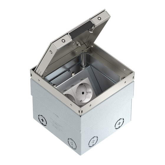
- Page 15 DE Montageanleitung Produktbeschreibung Bild : Quadratischer Geräteeinsatz für trocken ge- pflegte Bodenbeläge auf Estrich und für Sys- temböden, mit Bodenbelagaussparung für Bo- denbeläge von max . 15 mm Stärke . Mit Schnur- auslass im abnehmbaren Klappdeckel zur Leitungsausführung . Mit acht vorgeprägten Ein- führungsöffnungen für Installationsrohre M20 oder M25 . Der Rahmen ist durch vier Nivel- lierstützen auf Oberkante Bodenbelag ein- stellbar . Die Mindesteinbautiefe beträgt 95 mm, der N ivellierbereich +20 mm .
- Page 16 Einbauprinzip Bild : Geräteeinsatz Fugendichtung, z . B . Silikon Bodenbelag Estrich (oder Systemboden) Betonboden Klappdeckel öffnen und abnehmen K lappdeckel z . B . mit einem Schlitzschrau- bendreher öffnen . K lappdeckel wie gezeigt drehen und dann abnehmen . Geräteeinsatz montieren S teckdoseneinsatz ggf . durch Lösen der Be- festigungsschrauben entfernen und aufbe- wahren .
- Page 17 N ach Bedarf die vorgeprägten Rohr- einführungen z . B . mit einem Kreuzschrau- bendreher aushebeln: a uf- und ab bewegen für kleine Öffnung, ∅ 20 mm h in- und her bewegen für große Öffnung, ∅ 25 mm G eräteeinsatz mit geeignetem Befestigungs- material (z . B . Dübel und Schrauben) auf den Betonboden montieren .
- Page 18 Estrich verlegen K lappdeckel schließen, Stahlblechplatte und Montageab d eckung aufsetzen . Hinweis: Wir empfehlen, den Estrich ohne zu- sätzliche Trennlage zu verlegen . Zur Verminde- rung der Schallübertragung kann eine Trenn- lage verwendet werden, dies reduziert jedoch die feste Verankerung des Geräteeinsatzes im Estrich . E strich bündig mit Oberkante Montageab- deckung verlegen und an den Geräteeinsatz an a rbeiten . Elektroinstallation vornehmen M ontageabdeckung und Stahlblechplatte entfernen und entsorgen . Klapp d eckel öff-...
- Page 19 S teckdose wie gezeigt anschließen . PE-An- schluss des Geräteeinsatzes mit anschlie- ßen . T rennblende um 90° nach unten biegen (1.), Steckdose in den Geräteeinsatz einsetzen (2.) und festschrauben (3.) . Bodenbelag aufbringen und nivellieren B odenbelag aufbringen, dabei eine Deh- nungsfuge von 1–5 mm zum Geräteeinsatz belassen . F ür die Aussparung im Klappdeckel ein Passstück zuschneiden und, je nach Stärke des Bodenbelages, mit einer zusätzlichen Einlage bündig mit dem Außenrahmen des Klappdeckels in die Aussparung einkleben,...
- Page 20 D ehnungsfuge rund um den Geräteeinsatz mit einem geeigneten flexiblen Material (z . B . Silikon) verfüllen . Der fertig montierte Geräteeinsatz . Entsorgung – Verpackung wie Hausmüll – Geräteeinsatz wie Metallschrott Beachten Sie die örtlichen Müllentsorgungsvor- schriften .
-
Page 21: Technische Daten
Technische Daten UDHome2 V SA Artikelnummer 7427 022 Abmessungen 125 x 125 x 110 mm L x B x H Nivellierbereich + 20 mm Gewicht ca . 1,5 kg Einführungsöffnungen 8 x 25 mm (M25) Mindesteinbautiefe 110 mm Max . Einbauhöhe (Estrich/Systemboden + 130 mm Bodenbelag) Max . Höhe Bodenbelag 15 mm Schutzklasse bei Schnurauslass IP 40 / IP 20 geschlossen/geöffnet Bodenpflegeart trocken nach EN 50085-2-2 Einsatztemperatur- 5 – 60 °C bereich Steckdosentyp BS 546... - Page 23 EN Mounting instructions Product description Figure : Square service unit for dry-care floor coverings on screed and for system floors, with floor cover- ing cut-out for floor coverings of max . 15 mm thickness . With cord outlet in removable hinged lid for cable routing . With eight pre- marked entry openings for installation pipes M20 or M25 . The frame can be adjusted to the top edge of the floor covering using four...
- Page 24 Installation principle Figure : Service unit Joint seal, e .g . silicone Floor covering Screed (or system floor) Concrete floor Opening and removing the hinged lid O pen the hinged cover, e .g . with a slotted screwdriver . T urn the hinged lid as shown and then re- move it .
- Page 25 I f necessary, lever out the premarked pipe entries, e .g . with a Philips screwdriver . M ove up and down for a small opening, ∅ 20 mm M ove back and forth for a large opening, ∅ 25 mm M ount the service unit on the concrete floor with suitable fastening materials (e .g . an- chors and bolts) .
- Page 26 Laying the screed C lose the hinged cover and attach the steel plate and mounting cover . Note: We recommend routing the screed with- out an additional separation layer . A separation layer can be used to reduce noise transmission, although this reduces fixed anchoring of the ser- vice unit in the screed . L ay the screen flush to the top edge of the mounting cover and work it up to the service unit . Performing the electrical installation R emove the mounting cover and steel plate and dispose of them . Open the hinged lid .
- Page 27 C onnect the socket as shown . Also connect the PE connection of the service unit . B end the separation panel downwards by 90° (1.), insert the socket in the service unit (2.) and screw it tight (3.) . Applying the floor covering and adjusting the height Apply the floor covering, leaving an ex- pansion joint of 1–5 mm to the service unit . C ut out a key for the recess in the hinged lid and, depending on the thickness of the floor covering, stick it into the recess, flush to the exterior frame of the hinged lid, using an ad- ditional insert, e .g . with mounting adhesive . a nd Adjust the height of the top edge of the service unit, so that it is flush with the top edge of the floor covering . To do so, unscrew the four height adjustment supports accord- ingly, using a slotted screwdriver .
- Page 28 F ill the expansion joint around the service unit using a suitable flexible material (e .g . silicone) . The mounted service unit . Disposal – Packaging as household waste – Service unit as scrap metal Comply with the local waste disposal regula- tions .
-
Page 29: Technical Data
Technical data Type UDHome2 V SA Item number 7427 022 Dimensions 125 x 125 x 110 mm L x W x H Height-adjustment + 20 mm range Weight approx . 1 .5 kg Insertion openings 8 x 25 mm (M25) Minimum installation 110 mm depth Max . installation height (Screed/system floor + 130 mm floor covering) Max . floor covering 15 mm height Protection class for closed/opened cord IP 40 / IP 20 outlet Floor care type according to EN 50085-2-2 Use temperature range 5 – 60 °C Socket type BS 546... - Page 32 OBO Bettermann GmbH & Co. KG Postfach 1120 58694 Menden Germany www.obo-bettermann.com...
Need help?
Do you have a question about the UDHome2 V SA and is the answer not in the manual?
Questions and answers