Table of Contents
Advertisement
Quick Links
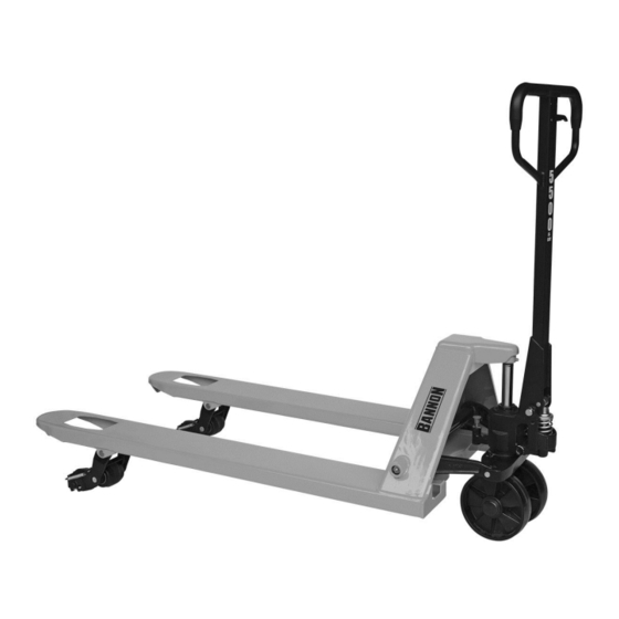
5500-Lb. Capacity Multi-Directional
Pallet Jack
Owner's Manual
WARNING:
Read carefully and understand all ASSEMBLY AND OPERATION
INSTRUCTIONS before operating. Failure to follow the safety rules and other basic safety
precautions may result in serious personal injury.
Item #55829
READ & SAVE THESE INSTRUCTIONS
Advertisement
Table of Contents

Related Manuals for Bannon 55829


Summary of Contents for Bannon 55829
- Page 1 Pallet Jack Owner’s Manual WARNING: Read carefully and understand all ASSEMBLY AND OPERATION INSTRUCTIONS before operating. Failure to follow the safety rules and other basic safety precautions may result in serious personal injury. Item #55829 READ & SAVE THESE INSTRUCTIONS...
- Page 2 Thank you very much for choosing a Bannon™ product! For future reference, please complete the owner’s record below: Serial Number/Lot Date Code: ________________________________ Purchase Date: ____________________________________________ Save the receipt, warranty, and this manual. It is important that you read the entire manual to become familiar with this product before you begin using it.
-
Page 3: Table Of Contents
Table of Contents Intended Use ............................4 Packaging Contents ..........................4 Technical Specifications ........................4 Important Safety Information ....................... 4 Specific Operation Warnings ....................... 5 Assembly Instructions .......................... 6 Operating Instructions .......................... 8 Maintenance ............................10 Troubleshooting ..........................12 Parts Diagram ............................13 Parts List .............................. -
Page 4: Intended Use
Intended Use The Bannon 5500 Lb. Capacity Multi-Directional Pallet Jack is designed for transportation of loads with a level, attached base and may be used only on a firm and even surface, such as concrete or asphalt. The load must be on evenly distributed pallets, with the ideal loading mode such that the center of gravity of the load is at the central position of the fork. -
Page 5: Specific Operation Warnings
WORK AREA SAFETY Inspect the work area before each use. Keep work area clean, dry, free of clutter, and well-lit. Cluttered, wet, or dark work areas can result in injury. Using the product in confined work areas may put you dangerously close to cutting tools and rotating parts. ... -
Page 6: Assembly Instructions
Do not operate a loaded pallet jack on ramps or inclines. Keep the load centered on the pallet jack. Wear steel toed boots while operating the pallet jack. Check for damaged parts before operating. Do not operate a damaged or faulty pallet jack. Do not attempt repairs unless you are trained or authorized to do so. - Page 7 1. Insert the base of the handle into the pump bracket (Figure 1). Align the holes at the base of the handle with the holes in the pump bracket. 2. Use a hammer to tap the handle pin into the holes of the pump bracket and handle (Figure 2). Use pliers to turn the handle pin until its holes align with the spring pin holes.
-
Page 8: Operating Instructions
4. Use a hammer to tap the spring pins (Figure 2) into the holes on the pump bracket and handle pin. 5. Tap out the pump retainer pin (Figure 1). NOTE: It is a good idea to remove any air bubbles that might have accumulated in the hydraulic system during shipping. - Page 9 Adjusting the Control Handle - 3 Positions On the Handle (1) of this pallet jack, you can find the Control Lever (7), which can be placed in three positions (See Figure 4): LOWER - to lower the load, pull up on the control lever. NEUTRAL - to place the control lever in this position while pulling the pallet jack or load.
-
Page 10: Maintenance
Figure 5 Maintenance Maintain the product by adopting a program of conscientious repair and maintenance in accordance with the following recommended procedures. It is recommended that the general condition of any tool be examined before it is used. Keep handles dry, clean, and free from oil and grease. The following chart is based on a normal operation schedule. - Page 11 Maintenance Interval Maintenance Point BLEEDING THE AIR. There may be times when the forks do not rise while pumping when in the "LIFT" position. Most likely this is because air has been introduced in to the hydraulic system. The air can be removed by moving the control handle to the "LOWER"...
-
Page 12: Troubleshooting
Troubleshooting Failure Possible Cause Corrective Action Make sure there is no oil leakage from Release Screw (35), Pressure Low oil level. Adjustment Screw (33) or valve area. Then add oil. Hydraulic unit does not lift Air in pump. See ''BLEEDING THE AIR''. Replace O-ring (refer to ''Seal and O- Worn O-ring in ram cylinder. -
Page 13: Parts Diagram
Parts Diagram Parts List Reference Part Number Part Description Qty. Remark Handle Spring Pin Blade Spring Spring Pin Roller Lever Mat Lever Mat Spring Pin Control Lever Oil Lite Bushing Release Rod Pressure Roller Spring Pin Oil Lite Bushing Handle Pin Spring Pin Spring Pin Hex Nut... - Page 14 Reference Part Number Part Description Qty. Remark Snap Ring Dust Seal Cap Pressure Adjust Screw Copper Washer Release Screw Spring Spring Base Steel Ball O-Ring Release Nozzle Base O-Ring Release Nozzle Release Nozzle Spring Oil Baffle Washer O-Ring Mid-Valve Base Oil Baffle Washer O-Ring Steel Ball...
-
Page 15: Replacement Parts
Reference Part Number Part Description Qty. Remark Spring Pin Oiler Rod Pin Spring Spring Pin Wheel Frame V Nut Screw Spring Pin Ball Bearing Wheel Wheel Axle Replacement Parts For replacement parts and technical questions, please call Customer Service at 1-800-222-5381. ... -
Page 16: Limited Warranty
Northern Tool and Equipment Company, Inc. ("We'' or ''Us'') warrants to the original purchaser only (''You'' or ''Your'') that the Bannon product purchased will be free from material defects in both materials and workmanship, normal wear and tear excepted, for a period of two years from date of purchase. - Page 17 Distributed by: Northern Tool & Equipment Company, Inc. Burnsville, Minnesota 55306 www.northerntool.com Made in China Page 17 of 17...
Need help?
Do you have a question about the 55829 and is the answer not in the manual?
Questions and answers