Table of Contents
Advertisement
INSTALLATION INSTRUCTIONS AND
INSTALLER / SERVICE TECHNICIAN:
Use the information in this manual for the installation / servicing and keep the document near the furnace
for future reference.
Communication wire connected between the indoor and outdoor units must be rated for at least 120VAC,
they are protected by the outdoor unit breaker and must be sized appropriatly.
Do not install any metering device on the indoor coil. The expension valve is located in the outdoor unit.
If a metering device is already installed in the indoor coil, it must be removed.
Both refrigerant lines must be separately insulated in order to avoid condensation and to ensure proper
efficiency.
HOMEOWNER:
Please keep this manual near the furnace for future reference.
CAUTION:
Do not tamper with the unit or its controls. Call a qualified service technician.
Printed in Canada on
100% recycled paper
HOMEOWNER'S MANUAL
COND-UHD
Liquid line dia (In)
Gas line dia (In)
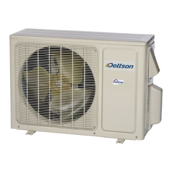
Models:
COND-UHD-09
COND-UHD-12
COND-UHD-18
COND-UHD-24
-09
-12
-18
-24
1/4
1/4
1/4
1/4
1/2
1/2
5/8
5/8
2020-05-08
Manufactured by:
Dettson Industries Inc.
Sherbrooke, Qc, Canada
www.dettson.com
X40259 Rev.A
Advertisement
Table of Contents

Subscribe to Our Youtube Channel
Related Manuals for Dettson COND-UHD-09


Summary of Contents for Dettson COND-UHD-09
- Page 1 HOMEOWNER: Please keep this manual near the furnace for future reference. CAUTION: Do not tamper with the unit or its controls. Call a qualified service technician. Manufactured by: Dettson Industries Inc. Sherbrooke, Qc, Canada www.dettson.com Printed in Canada on 2020-05-08 X40259 Rev.A...
-
Page 2: Table Of Contents
Table of Contents List of Figures Figure 1: Installation and Clearances ..SAFETY Figure 2: Winting Interface Board to ODU . . Figure 3: Indoor Coil Sensor Location ..1.1 Warning ......Figure 4: Tube Tightening . -
Page 3: Safety
• Have all wiring connected tightly. Loose con- nections may lead to overheating and a possible fire hazard. All installation or repair work shall SAFETY be performed by your dealer or a specialized subcontractor as there is the risk of fire, electric Installing, starting up, and servicing air conditioner shock, explosion or injury. -
Page 4: Specifications
2 Specifications Table 1 – Outdoor Unit Specifications Model COND-UHD-09 COND-UHD-12 COND-UHD-18 COND-UHD-24 Power Supply 208/230 VAC, 60 Hz, 1 phase Cooling Capacity (min-max) BTU/h 9000 (1535-12996) 12000 (2900-15354) 18000 (4094-21837) 22000 (6800-30700) Heating Capacity (min-max) BTU/h 9000 (2388-13648) 12200 (3071-18766) 18000 (4094-24566) 24000 (6800-32000) -
Page 5: Installation
• The site should be able to withstand the full weight and vibration; • Select a dry place, and do not expose the unit to 3 Installation direct sunlight nor strong winds; • Make sure that the outdoor unit is installed in 3.1 Notices accordance with the installation instructions, and is convenient for maintenance and repair;... -
Page 6: Clearances
Installation of the interface card is made easy on the Condensate Drain Dettson’s Chinook and Supreme furnaces. Installation Coils are equipped with multiple drain connections. port has been designed on these furnaces. Refer to the... -
Page 7: Outdoor Unit
3.7 Outdoor Unit for installation location and thermostat wiring. Wire to the outdoor unit as shown in the figure. Electrical Wiring Figure 2 – Winting Interface Board to ODU 1. Remove the handle on the right side plate of outdoor unit; 2. -
Page 8: Connection Pipes
Table 3 – Checklist After Installation Items to be checked Possible malfunction Has the unit been fixed firmly? The unit may drop, shake or emit noise Has the refrigerant leakage test been performed? It may cause insufficient cooling (heating) Is thermal insulation sufficient? It may cause condensation Is water drainage satisfactory? It may cause water leakage... -
Page 9: Troubleshooting
4 Troubleshooting 4.1 Interface Board Figure 5 – Interface Board Table 4 – Interface Board Display... -
Page 10: Outdoor Unit Error Codes
4.2 Outdoor Unit Error Codes Table 5 – Outdoor Unit Error Codes LED Flashes # Malfunction Status Causes Yellow Red Green 1 High pressure protection Unit stops Poor exchange (blockage), ambiant temperature too high, too much refrigerant 2 Anti-freeze protection ODU stops in cooling Poor air exchange (IDU), abnormal fan speed, dirty evaporator 3 Lack of refrigerant Unit stops... -
Page 11: Commissioning Checklist
5 Commissioning Checklist Indoor Unit: ______________ s/n#: ______________ Figure 6 – ODU Serial Number Location Outdoor Unit: ______________ s/n#: ______________ Filter is clean Line length: ________ ft Line height: ________ Temp sensor position at mid-height on A-coil A-coil orifice removed Error code: ________ Temp rise through the coil: T before:... -
Page 12: Replacement Parts
6 Replacement Parts Figure 7 – Exploded View 9k and 12k... -
Page 13: Table 6: Parts List 9K And 12K
Table 6 – Parts List 9k and 12k Description COND-UHD-09 COND-UHD-12 Front grill 016004060004 016004060004 Front panel assy 000003060115 000003060115 Fan motor 1501308507 1501308507 Clap board 01233510 01233510 Chassis sub assy 0280311901P 0280311901P Compressor and fitting 00103977 00103977 Valve support sub assy... -
Page 14: Figure 8: Exploded View 18K And 24K
Figure 8 – Exploded View 18k and 24k... -
Page 15: Table 7: Parts List 18K And 24K
Table 7 – Parts List 18k and 24k Description COND-UHD-18 COND-UHD-24 Front grill 016004060005 016004060005 Front panel assy 0153501405 0153501405 Front side plate 01303249P 01303249P Chassis sub assy 02803315P 017000000166P Electrical heater 7651000411 7651000411 Compressor and fitting 00105251 00105251 4 way valve assy 030152000081 030152000081 Electronic expansion valve assy...
Need help?
Do you have a question about the COND-UHD-09 and is the answer not in the manual?
Questions and answers