
Related Manuals for EEC SE Series

Summary of Contents for EEC SE Series
- Page 1 SE Series SE 7430/SE 7440/SE 7441/SE 7451/SE 7452 Electrical Safety Analyzer User Manual E2.00...
- Page 3 (2) year from date of shipment. During the warranty period, you must return the instrument to EEC or its branches or its authorized distributor for repair. EEC reserves the right to use its discretion on replacing the faulty parts or replacing the assembly or the whole unit.
-
Page 5: Table Of Contents
1.5.3 Ground Bond Test ....................10 1.5.4 Run Test ......................... 10 1.5.5 Touch Current Test ....................11 1.6 Key Features and Benefits: SE Series ............... 12 2. Getting Started ................... 14 2.1. Unpacking and Inspection ..................14 2.1.1 Packaging ....................... 14 2.1.2 Returning the Instrument .................. - Page 6 4.3.4 User Interface ......................40 4.3.5 Information ......................43 4.3.6 Import and Export System and Test Data .............. 43 4.4 SECURITY........................ 46 4.5 FAILCHEK ........................ 48 4.5.1 Continuity FAILCHEK (Opt.7002 , Opt.7006) ............48 4.5.2 Ground Bond FAILCHEK ..................49 4.5.3 AC Hipot FAILCHEK ....................
- Page 7 9.1 Warranty Requirements ..................95 9.2 Calibration Initialization ..................95 9.3 Calibration of Parameters ..................96...
-
Page 9: Introduction
1. Introduction 1.1 Safety Symbols 1.1.1 Product Marking Symbols Product will be marked with this symbol when it is necessary to refer to the operation and service manual in order to prevent injury or equipment damage. Product will be marked with this symbol when hazardous voltages may be present. Product will be marked with this symbol at connections that require earth grounding. -
Page 10: Glossary Of Terms
1.2 Glossary of Terms Alternating Current, AC: Current that reverses direction on a regular basis, commonly in the U.S.A. 60 per second, in other countries 50 times per second. Breakdown: The failure of insulation to effectively prevent the flow of current sometimes evidenced by arcing. -
Page 11: Safety
The instrument, its power cord, test leads, and accessories must be returned at least once a year to EEC customer support department for calibration and inspection of safety related components. EEC will not be held liable for injuries suffered if the instrument is not properly maintained and safety checked annually. -
Page 12: Test Operator
test station. Signs should be posted: "DANGER - HIGH VOLTAGE TEST IN PROGRESS - UNAUTHORIZED PERSONNEL KEEP AWAY." Work Area Perform the tests on a non-conducting table or workbench, if possible. If you cannot avoid using a conductive surface, be certain that it is connected to a good earth ground and the high voltage connection is insulated from the grounded surface. -
Page 13: Instrument Connections
will flow through any available ground path. Rules Operators should be thoroughly trained to follow all of the aforementioned rules, in addition to any other applicable safety rules and procedures. Defeating any safety system should be considered a serious offense with severe penalties such as removal from the Hipot testing job. Allowing unauthorized personnel in the area during a test should also be dealt with as a serious offense. -
Page 14: Key Safety Points To Remember
When testing with DC, always discharge the capacitance of the item under test and anything the high voltage may have contacted--such as test fixtures--before handling it or disconnecting the test leads. HOT STICK probes can be used to discharge any capacitance in the device under test as a further safety precaution. -
Page 15: The Different Types Of Safety Tests
1.5 The Different Types of Safety Tests 1.5.1 Dielectric Withstand Test The principle behind a dielectric voltage - withstand test is simple. If a product will function when exposed to extremely adverse conditions, it can be assumed that the product will function in normal operating circumstances. - Page 16 Weak Insulating Materials Pinholes in Insulation Inadequate Spacing of Components Pinched Insulation Dielectric Withstand Test; AC verses DC Please check with the Compliance Agency you are working with to see which of the two types of voltages you are authorized to use.
- Page 17 This can make it very difficult to detect products that have excessively high leakage current. Another disadvantage of AC testing is that the hipot has to have the capability of supplying reactive and leakage current continuously. This may require a current output that is actually much higher than is really required to monitor leakage current and in most cases is usually much higher than would be needed with DC testing.
-
Page 18: Insulation Resistance Test
1.5.2 Insulation Resistance Test Some "dielectric analyzers today come with a built in insulation resistance tester. Typically, the IR function provides test voltages from 500 to 1,000 volts DC and resistance ranges from kilohms to gigaohms. This function allows manufacturers to comply with special compliance regulations. BABT, TÜ... -
Page 19: Touch Current Test
powered up immediately after the safety tests are completed with a single connection to the DUT. Measurements that are commonly made while the DUT is running can include Amperage, Voltage, Watts and Power Factor. 1.5.5 Touch Current Test The Line Leakage test is one of many product safety tests that are normally specified for electrical products by safety testing agencies such as Underwriters Laboratories (UL) and the International Electrotechnical Committee (IEC). -
Page 20: Key Features And Benefits: Se Series
1.6 Key Features and Benefits: SE Series Alerts the operator that the machine is due for 1.CAL-ALERT calibration in advance of the calibration due date. Two test modes allow for a basic Continuity test to be performed simultaneously with the Hipot test, or a 2.TWO CONTINUITY TEST MODES... - Page 21 operate the SE through simple PLC relay control. Allows the operator to self-verify the instrument’s 11.FAIL-CHEK failure detectors. Allows the operator to set multiple dwell cycles at 12.PRO-VOLT * different voltages for ACW/DCW/IR so that test voltages can be raised and held in steps Connect a barcode scanner directly to the instrument 13.BARCODE SCANNING front panel and perform the appropriate tests.
-
Page 22: Getting Started
If the shipping carton is damaged, inspect the contents for visible damage such as dents, scratches or broken display. If the instrument is damaged, notify the carrier and EEC's customer support department. Please save the shipping carton and packing material for the carriers inspection. Our customer support department will assist you in the repair or replacement of your instrument. -
Page 23: Power Requirements
2.2.2 Power Requirements This instrument requires a power source of either 100 - 120 volts AC ± 10%, 50/60 Hz single phase or 200 - 240 volts AC ± 10%, 50/60 Hz single phase. Please check the rear panel to be sure the proper switch setting is selected for your line voltage requirements before turning your instrument on. - Page 24 This instrument may be stored or shipped in environments with the following limits: Temperature....- 40°- 75°C Altitude....…..25000 feet (7,620 meters) The instrument should also be protected against temperature extremes that may cause condensation within the instrument. Ventilation: Do not block any ventilation openings, insure that there is at least 6 inches (15 cm) of space from the rear panel to any wall or obstruction behind the unit.
-
Page 25: Specifications And Controls
3. Specifications and Controls 3.1 Specifications Model CONT. Built-in Scanner Option SE 7430 Option (8W or 8W+8Cont.) SE 7440 Option SE 7441 Option SE 7451 Option SE 7452 Option MODEL SE 7430 SE 7440 SE 7441 SE 7451 SE 7452 AC WITHSTAND VOLTAGE Output Rating 5KVAC/40mA... - Page 26 MODEL SE 7430 SE 7440 SE 7441 SE 7451 SE 7452 0, 0.1-999.9 Auto Range (0=continuous) Dwell Time, Second ±(0.1% of Setting + 0.05s) 0, 0.2-999.9 Fixed Range (0=continuous) 0.000-40.00mA(Total current + current Offset ≤40mA) for SE 7430 & SE 7440 & SE 7441 Current Offset 0.000-100.0mA(Total current + current Offset ≤100mA) for SE 7451 &...
- Page 27 0.0-10000uA(Total current + current Offset ≤10mA) Current Offset Arc Detection The range is from 1-9(9 is the most Sensitive) MODEL SE 7430 SE 7440 SE 7441 SE 7451 SE 7452 INSULATION RESISTANCE Output Rating 6KVDC/50000MΩ Output Voltage, Vdc 10-6000 ±(1% of Setting + 0.5% of Range) 0.10-99.99 0.01 (HI-Limit:0 = OFF)
- Page 28 Measurement Range Resolution Accuracy Voltage, KV(AC/DC) 0.00-7.50 0.01 ±(1% of reading + 0.5% of Range) 0-1000 ±(1% of reading + 0.5% of Range) Voltage, Vdc (IR only) 1001-6000 ±(1% of reading + 0.5% of Range) 0.000-3.500 0.001 ±(2% of reading + 3 counts) 3.00-40.00 0.01 (SE 7430 , SE 7440 , SE 7441)
- Page 29 GENERAL 100-120Vac/200-240V ± 10% auto range, 50/60Hz ± 5%, max. current 6.3A for SE 7430, SE 7440 & SE 7441 Input Voltage AC 100-120Vac/200-240V ± 10% auto range, 50/60Hz ± 5%, max. current 15A for SE 7451 & SE 7452 Input:Test, ReSet, Interlock, Recall File 1 through 15 PLC Remote Control Output:Pass, Fail, Test-in-Process...
-
Page 30: Instrument Controls
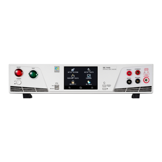
3.2 Instrument Controls 3.2.1 Front Panel Controls SE 7430 and SE 7451 SE 7440 and SE 7452 SE 7441... - Page 31 POWER SWITCH: Powers the test instrument ON or OFF. RESET BUTTON: Resets the instrument. If a failure condition occurs during a test, pressing this button will reset the system, shut off the alarm and clear the failure condition. The Reset button must be pressed before performing another test or changing any of the setup parameters.
- Page 32 12. CURRENT OUTPUT TERMINAL: Connector used to attach the high current output lead, adapter box high current lead or test fixture high current lead to the instrument. This connection provides the output current for the ground bond and continuity.
-
Page 33: Rear Panel Controls
3.2.2 Rear Panel Controls SE 7430 SE 7440 SE 7441... - Page 34 SE7450 SE 7452 SCANNER CONNECTOR: For connection of optional external Scanner. REMOTE SIGNAL OUTPUT: 9-Pin D sub-miniature female connector for monitoring PASS, FAIL, and PROCESSING output relay signals. REMOTE SIGNAL INPUT: 9-Pin D subminiature male connector for remote control of TEST, RESET, and REMOTE INTERLOCK DISABLE functions, as well as MEMORY SELECTION BUS INTERFACE: Standard connector for interconnection to the RS-232 Bus interface.
- Page 35 REAR PANEL CONTINUITY OUTPUT TERMINAL (OPT.7002) : 2 continuity output connector in parallel with the front panel output. CALIBRATION BUTTON: To put the instrument into the calibration mode push this button and turn on the power switch simultaneously. FUSE RECEPTACLE: To change the fuse, unplug the power (mains) cord and turn the fuse receptacle counter-clockwise.
-
Page 36: Programming Instructions
4. Programming Instructions 4.1 Using the Touch Screen The touch screen display of the SE provides full control of the instrument. The touch screen will be used to setup system and test parameters as well as security setup and calibration. SE’s touch screen functions just like any other touch screen. -
Page 37: Main Menu
Touch The various screens of the SE will display icons and parameters. Touch the appropriate icon or parameter with the fingertip as shown in the image below: Scroll and Swipe A scroll bar on the right side of the screen indicates that there are additional parameters or features. -
Page 38: Setup System
The default screen is the main menu screen of the instrument. From this screen all the functions and settings of the instrument can be accessed: Setup System – instrument global parameters such as time and date, calibration and hardware. Perform Tests – navigate to the Perform Tests screen in order to run a test sequence. Security –... -
Page 39: Calibration Alert
4.3.1.1 Set Date Use the touchscreen numeric keypad to enter the desired value for the date, month and year. Upon entering a value the enter key ( ↵) will appear. Touch the enter key to save the value and move to the next field. The < (back arrow) key can be used to toggle between date, month and year. - Page 40 The first field under the Calibration Alert screen allows the user to set the Calibration Alert to ON or OFF. Touch the desired value and the enter key ( will appear. Press the enter key to save the value ↵) and move to the next parameter under the Calibration Alert menu.
-
Page 41: Hardware
4.3.3 Hardware The Hardware menu contains important system parameters which must be set prior to performing tests. Touch the Hardware icon and the following screen will appear: The touchscreen can be scrolled downward to see the remaining Hardware parameters. Upon scrolling down the remaining items appear as follows: 4.3.3.1 Smart GFI The high voltage power supply of the SE is internally referenced to earth ground. - Page 42 The Smart GFI is an adjustable function ranging from 0.5 - 5.0mA. Setting the Smart GFI value to 0mA will simply turn the function OFF. To set the Smart GFI enter the desired value using the touchscreen keypad and touch the enter key ( to save the value and move on to the next ↵) parameter.
- Page 43 4.3.3.6 Baudrate The transmission speed of RS232 can be set, it has 9600, 19200, 38400, 57600 and 115200 selectable. Note: the faster the transmission speed setting will be interference. 4.3.3.7 ProVOLT The ProVOLT function allows for maintaining, stepping up or stepping down the voltage output between steps without the voltage dropping to 0V.
- Page 44 when the Control mode is 7730 or 7400. 4.3.3.14 Barcode The Barcode function allows the user to connect a barcode scanner directly to the front panel of the instrument’s barcode port. This is utilized to enter product and serial number information for testing.
- Page 45 There are two options under Barcode, Barcode I/P and Autostart. Touch the Barcode I/P icon and the following screen will appear: The Barcode I/P function can be set to OFF, SERIAL, PROD CHEK/SER, PROD/SER1/SER2, PROD/SER, PROD one/SER and PRODUCT. SERIAL: Only scan the SERIAL number.
- Page 46 When the setting is SERIAL, PRODUCT or PROD/SER the user can scan barcodes in the Perform Tests screen before the test is started. When the barcode is scanned, one of the following messages will appear on the display: After the barcodes are scanned, pressing TEST will initiate the test sequence. Pressing RESET will abort the TEST sequence.
- Page 47 the exact alpha-numeric code that is on the product’s barcode label. For example, if Product A has barcode “123456789”, then the test file that the user would like to run when testing Product A must be named “123456789”. Upon scanning the barcode, the SE will immediately load the test associated with that barcode.
-
Page 48: User Interface
Location Select Int. memory if you wish to store the test results on the onboard instrument memory. Select USB disk if you wish to save the test results on an external USB flash drive. For best results use the USB flash drive provided by Associated Research. Test Result Select PASS to save the results of the steps that passed. - Page 49 Scroll downward to see the remaining options under the User Interface: 4.3.4.1 Results The next parameter under User Interface is Results. This allows the user to set the desired results display after a test sequence has been run. The Results function can be set to ALL, LAST or P/F (Pass/Fail).
- Page 50 Fail screens will appear as follows: Touch the screen to select the desired value and the enter key ( ↵) to save the selection and move to the next parameter. 4.3.4.2 Touch Sound Select Touch Sound icon on and choose between ON and OFF. If Touch Sounds = ON, the instrument will emit a short audible beep anytime the screen is touched.
-
Page 51: Information
4.3.4.7 Hardware Key This function applies to the test operators need to wear gloves. Press My Menu / Select and key to adjust the output voltage when user has wear gloves. When the Hardware Key is turned ON, the My Menu / Select key is increment voltage, key is decrease voltage at during output. - Page 52 Import Select the Import icon and the following screen will appear: There are four different Import options available. All the options will import the appropriate files from the connected USB disk: System – Import System file One File – Import a single Test file System and All Files –...
- Page 53 If the Test file name already exists in the instrument internal memory the following warning message will appear on the screen: Export Select the Export icon and the following screen will appear: There are four different export options available. All the options will export the appropriate files into the connected USB disk: System –...
-
Page 54: Security
following confirmation screen will appear: If the Test file with the same name already exists on the USB disk the following message will appear: 4.4 SECURITY From the Main Menu select Security and the following screen will appear: The first option under Security allows the user to set Security to ON or OFF. Select Security using the touchscreen keypad and choose between ON or OFF. - Page 55 To add a user, select the Add User icon and the following screen will appear where an alpha- numerical user ID can be entered and saved. After the User ID is entered, the next screen will ask for entering a Password for the newly added User ID.
-
Page 56: Failchek
NOTE: whenever a user’s security level is Run Only, you may only start at test step 1. Once a user has been successfully added the User Setup screen will display the newly added user. From this screen the user settings can be edited: 4.5 FAILCHEK FAILCHEK is the process by which an instrument’s failure detectors are proven to be functioning properly. -
Page 57: Ground Bond Failchek
If the FAILCHEK test fails, the following screen will appear: 4.5.2 Ground Bond FAILCHEK To perform Ground Bond FAILCHEK, touch the Ground Bond icon and the following screen will appear: Follow the instructions on the screen. Press the Test button on the front panel of the instrument to start the test. -
Page 58: Ac Hipot Failchek
If the FAILCHEK test fails, the following screen will appear: 4.5.3 AC Hipot FAILCHEK To perform an AC Hipot FAILCHEK, touch the AC Hipot icon and the following screen will appear: Follow the instructions on the screen. Press the Test button on the front panel of the instrument to start the test. -
Page 59: Dc Hipot Failchek
4.5.4 DC Hipot FAILCHEK To perform a DC Hipot FAILCHEK, touch the DC Hipot icon and the following screen will appear: Follow the instructions on the screen. Press the Test button on the front panel of the instrument to start the test. If the FAILCHEK test passes, the following screen will appear: If the FAILCHEK test fails, the following screen will appear:... -
Page 60: Ir Failchek
4.5.5 IR FAILCHEK To perform an IR FAILCHEK, touch the IR icon and the following screen will appear: Follow the instructions on the screen. Press the Test button on the front panel of the instrument to start the test. If the FAILCHEK test passes, the following screen will appear: If the FAILCHEK test fails, the following screen will appear:... -
Page 61: Test Parameters
4.6 Test Parameters This section details the various test parameter descriptions. For information on setting up test sequences, refer to section 4.7. Setup Tests. From the Main Menu select Setup Tests and the following screen will appear: 4.6.1 Description of Test Parameters This section details each test parameter and test parameter description. - Page 62 threshold that triggers a failure when not exceeded. Min Lmt R: ACW test only. Real current minimum limit. The minimum current or resistance threshold that triggers a failure when not exceeded. Max Lmt: The maximum current or resistance threshold that triggers a failure when exceeded. Min Lmt: The minimum current or resistance threshold that triggers a failure when not exceeded.
-
Page 63: Additional Parameter Notes And Functions
Scanner or EX Scanner: (This parameter will only be seen on units equipped with a scanner). The high voltage channels can be set to a High (H) or Low (L) level giving the operator the capability to test from one channel to another channel or from any channel to a common Low or Return point. The channels can be connected in parallel if desired but there is only one leakage current measurement for all channels. - Page 64 Ramp-HI The Ramp-HI function is active during the Ramp period only. Ramp-HI will allow current higher than the normal Max-Lmt current setting of the DC Withstand Voltage test to avoid false failure due to charging current. Charge–LO The Charge-LO function is used to check if the cables are connected properly at the beginning of a test.
- Page 65 From the Main Menu select Setup Tests and the following screen will appear: Touch the Add File icon and enter a name for the new file using the touchscreen keypad and use the enter key ( to save the name and move to the next screen. ↵) Next, add a test to the newly created test file: Touch the Add Step icon to enter the test parameters screen.
-
Page 66: Acw
4.7.1 ACW Touch ACW for the test type and use the enter key ( to save the Test Type and move to the next ↵) test parameter: Note: The Offset value can only be set by performing the auto offset. To perform an auto offset disconnect the DUT and leave all the test leads open. -
Page 67: Dcw
4.7.2 DCW Select DCW for the test type and use the enter key ( to save the Test Type and move to the next ↵) test parameter: Note: 1. Charge-Lo: The parameter can be set automatically or manually. To perform an auto Charge- Lo, connect the DUT and all the test leads as needed to perform a real test. -
Page 68: Gnd
4.7.3 IR Select IR for the test type and use the enter key ( to save the Test Type and move to the next ↵) test parameter: Note: Charge-Lo: The parameter can be set automatically or manually. To perform an auto Charge- Lo connect the DUT and all the test leads as needed to perform a real test. -
Page 69: Continuity (Opt.7002)
4.7.5 Continuity (Opt.7002) Select Continuity for the test type and use the enter key (↵) to save the Test Type and move to the next test parameter: 4.7.6 View Test Files Once all tests have been programmed and saved, navigate to the Main Menu. Select the Setup Tests icon and select the test file that was previously created. -
Page 70: Perform Tests
4.8 PERFORM TESTS From the main menu select the Perform Test icon and the following screen will appear: This screen will display the first test that was saved in the test file. If there are multiple test files saved in the instrument select the Load icon and all the test files will be displayed: The user can select the desired test file and the first test step in the selected test file will be displayed. - Page 71 two small meters on the top of the screen display the Hi Limit Real and Dwell Time. Touch any of the parameters and drag it on to the location of a different parameter and the two meters will be swapped. For example in the next screen the Hi Limit Total is the smaller meter and the Hi Limit Real is the bigger meter.
- Page 72 Date The following System parameters will not be affected by the system initialization: Setup Sys. Cal Date No change Cal Due No change Alert No change Date No change Time No change Security Password No change Security No change...
-
Page 73: Test Connections
5. Test Connections 5.1 Connecting the Test Leads The instrument comes with all cables necessary for performing a Hipot and Continuity test. Plug the red alligator clip into the HV receptacle on the SE. Connect one of two black alligator clip leads to the Return receptacle and the other to the Cont. -
Page 74: Results Screens
6. Results Screens After a test has completed the Results icon will be available on the screen. For example: Select the Results icon to enter the results screen. The Results screen will appear as follows: The Results screen allows you to view the results of the last test step the instrument performed and the results of the previously performed tests. - Page 75 Touch and hold any test step result on the previous screen and a new screen will pop up: From this screen you can transfer All results to a USB disk, delete All results or delete a single result. To transfer results to a USB disk select the Transfer icon and a new pop up screen will appear where a file name must be entered for the results file.
-
Page 76: Error Messages And Fail Messages
Selecting Delete All function will simply delete all the test results from the internal memory. Selecting Delete will delete a selected step. 6.1 Error Messages and Fail Messages If there is an error during testing, the error description will be displayed on the screen. Below is a list of error messages that the SE reports: Abort: This message appears on the display if the test in process is aborted with the RESET button or remote Reset control. - Page 77 Perform Test screen. Fatal Error: If the instrument has a Fatal Error failure then the following screen will appear: All of the buttons and keys are not active in this situation. You should contact EEC to receive further instruction. Fatal Error identification number will represent type of the failure that occurs.
- Page 78 DATA hole insert unrecognized DISK, or BARCODE hole USB device error.(22) insert unrecognized BARCODE USB device error.(23) Search HU4 file error USB device error.(24) Delete file error USB device error.(26) USB device error Does not support this USB DISK format error. It support FAT16 and FAT32 device.(61) EE ERROR Abnormal code read when during reading step...
-
Page 79: Connection Of Remote I/O
7. Connection of Remote I/O Two 9-pin “D” type connectors mounted on the rear panel provide REMOTE-INPUT-OUTPUT control and information. These connectors mate with a standard 9 pin D-sub-miniature connector provided by the user. The output mates to a male (plug) connector while the input mates to a female (receptacle) connector. -
Page 80: Remote Signal Inputs And Memory Access
PASS – The relay contact closes the connection between pin (1) and pin (2) after detecting that the item under test passed all tests. The connection is opened when the next test is initiated or the reset function is activated. FAIL –... - Page 81 PROVOQUER DES DOMMAGES AU CIRCUIT DE CONTRÔ LE Remote Interlock SE series is equipped with a Remote Interlock feature. Remote Interlock utilizes a set of closed contacts to enable the instrument’s output. If the Remote Interlock contacts are open the output of the instrument will be disabled.
- Page 82 button is pushed, a pop-up message will be displayed on the screen for two seconds. The message will appear as follows: If the Remote Interlock contacts are opened during a test, the pop-up message will be displayed and the test will abort. The hardware and has been configured to provide the interlock connections on pins 4 and 5 of the Remote Interface, Signal Input port.
-
Page 83: Bus Remote Interface Gpib / Usb / Rs-232
USB / RS-232 interface. Please refer to the Option section of this manual for details on the SE SERIES options. The USB / RS-232 interface also uses the same command set as the GPIB interface for setting of test parameters. However there are many functions of the GPIB 488.2 interface that are not available through USB / RS-232. -
Page 84: Sending And Receiving Commands
8.1.3. Sending and Receiving Commands Sending Data Once a command is sent to the instrument over the RS-232 bus the instrument will send one of two responses. If the transfer was recognized and completed the instrument will return with 06 hex or 6 decimal, the Acknowledge (ACK) ASCII control code. -
Page 85: Interface Functions
of the SE to any value between 0 and 30. The address can only be set from the front panel. The address is stored in non-volatile memory and does not change when the power has been off or after a remote reset. ... - Page 86 8.4.1 Rules for Sending Commands to the Instrument The following conventions are used to describe the commands syntax for SE: Braces ({ }) enclose each parameter for a command string. Triangle brackets (< >) indicate that you must substitute a value for the enclosed parameter. ...
- Page 87 8.4.3 File Editing Commands The following commands are used to create or modify Test Setup Files. Commands should be separated from parameters by a space. If multiple parameters are entered, they should be separated by commas. COMMAND DESCRIPTION VALUE FL <memory number>...
- Page 88 SS <step number> Selects the active selected step to load into RAM. The step must first be selected before any specific parameters can be edited. SAA, SAD, SAI, SAG, SAC These commands add the appropriate test type within the memory at the step location that has been selected.
- Page 89 ADD2 IR,Voltage,HI-Limit,LO-Limit,Ramp UP,Delay Time,Dwell Time,Ramp SCANNER install, Down,Charge LO,Scanner Setup Scanner Setup parameter exise ADD2 GND,Current,Voltage,HI-Limit,LO-Limit,Dwell Time, SCANNER install, Offset,Frequency,Scanner Channel Scanner Channel parameter exise ADD2 CONT.,HI-Limit,LO-Limit,Dwell Time,Offset,Scanner Channel SCANNER install, Scanner Channel parameter exise When Continuity delay option is off. LS2? &...
- Page 90 ADD3 all parameters for one STEP n=type, p=parameters ADD3 ACW,Voltage,HI-Limit T,LO-Limit T,Ramp Up,Dwell Time,Ramp Down, SCANNER install, Arc Sense,HI-Limit R,LO-Limit R,Offset,Frequency,Arc Dectect,Continuity, Scanner Setup Range,Scanner Setup parameter exise ADD3 DCW,Voltage,Output Polarity,HI-Limit,LO-Limit,Ramp Up,Dwell Time, SCANNER install, Ramp Down,Charge LO,Arc Sense,Offset,Ramp-HI,Arc Dectect,Continuity, Scanner Setup Range,Low Range,Scanner Setup parameter exise...
- Page 91 SP <prompt message> Adds or edits a prompt message for the active step. Removes or deletes the prompt that had been created for the active step. 8.4.4 Test Parameter Editing Commands and Companion Queries These commands are used to modify the test parameter within each step. These commands require a parameter value to be included with the command.
- Page 92 COMMAND NAME TEST VALUE TYPES EDW < value > Edit Dwell 0, 0.4 - 999.9s EDW? 0, 0.4 - 999.9s 0, 0.5 - 999.9s 0, 0.5 - 999.9s CONT 0, 0.3 - 999.9s EDE < value > Edit Delay 0.5 – 999.9s EDE? EO <...
- Page 93 COMMAND NAME TEST VALUE TYPES ES xxxxxxxx…. Edit Scanner-HLO xxxxxxxx=H,L,O xxxx CONT ESN nn Edit Scanner nn=1~16 or 24 by Model ESN? EIS xxxxxxxx…. Edit Scanner-HLO xxxxxxxx=H,L,O EIS? xxxx CONT EES xxxxxxxx…. Edit Scanner-HLO xxxxxxxx=H,L,O EES? xxxx CONT ERG n Edit Range n=0-1 ERG?
- Page 94 COMMAND NAME VALUE SAF < value > ARC Frequency 1=10k-150k Hz, 0=10k-30k Hz SAF? SR < value > Results 0=LAST, 1=ALL, 2=P/F SCA < value > Cal Alert 1= On, 0=Off SCA? SCDA < value > Cal Date 0=ymd, 1=mdy, 2=dmy SCDA? SCDU <...
- Page 95 COMMAND NAME VALUE SEAF nnnnnnnn Export All File nnn=name SEAD nnnnnnnn Export All Data nnn=name SMM n Home Screen n=0-2, 0= Menu, 1= Perform Tests, SMM? 2=My Menu SAN n Animation n=0-1 SAN? 0=Continue, 1=Pause SLA n Language n=0-2, SLA? 0=English, 1=Traditional Chinese 3=Simplified Chinese SAV n...
- Page 96 COMMAND NAME VALUE Name: 8 character max Password: 8 number max Level: 0=Run Only, 1=Recall Setup, 2=Edit Step, 3=Full System SUD n User Delete n=1-5 SUE p,p,p,p User Edit SUA Pointer,Name,Password,Level Pointer: 1-5 Name: 8 character max Password: 8 number max Level: 0=Run Only, 1=Recall Setup, 2=Edit Step,...
- Page 97 COMMAND NAME VALUE Read Scanner Status 0=None, 1=Int, 2=Ext 1, 3=Int+Ext 1, 4=Ext 2, 5=Int+Ext 2, 6=Ext 1+Ext 2, 7=Int+Ext 1+Ext 2 Read USB Stick 0=NO, 1=YES FR nnnn File Rename nnn=name List File Name Active selected memory LF nn? List File Name Active selected file List Prompt...
- Page 98 *ESR?, *ESE, *ESE? and *STB? COMMAND NAME DESCRIPTION *IDN? Identification Query EEC, Model Number, Serial Number, Firmware Revision *RST Reset Command Resets SE series...
- Page 99 Service Request Enable Query 0 - 255 *IDN? Read the instrument identification string. Company = EEC *RST Reset the instrument to original power on configuration. Does not clear Enable register for Standard Summary Status or Standard Event Registers. Does not clear the output queue. Does not clear the power-on-status-clear flag.
- Page 100 *OPC? Returns an ASCII "1" after the command is executed. *WAI After the command is executed, it prevents the instrument from executing any further query or commands until the no-operation-pending flag is TRUE. *PSC {1|0} Sets the power-on status clear bit. When set to 1 the Standard Event Enable register and Status Byte Enable registers will be cleared when power is turned ON.
- Page 101 automatically clears the register and sets all bits to inactive state or 0. When querying an Event register the information is returned as a decimal number representing the binary-weighted sum of all bits within the register. The Enable registers bits represent the selection of bits that will be logically OR’d together to form the summary bit in the Status Byte.
- Page 102 This means that bit 6 and bit 0 are set to a value of 1. After reading the Status Byte the Status Byte value will change to 01 hex.
-
Page 103: Calibration
EEC offers a standard one-year manufacture’s warranty. This warranty can be extended an additional four years provided that the instrument is returned each year to EEC for it’s annual calibration. In order to be eligible for the extended warranty instruments must be returned to EEC for calibration service at least once every twelve months. - Page 104 Scroll down on the screen to view the next page which will appear as follows: Scroll down on the screen to view the next page which will appear as follows: 9.3 Calibration of Parameters From the Calibration screens, use the touchscreen to select the parameter you wish to calibrate. A calibration prompt screen will now appear that describes the necessary load and connection information for the parameter being calibrated.
- Page 105 Calibration of AC Hipot Voltage Connect the standard 5KVAC kilovolt meter from H.V. to Return. When the standard voltmeter is connected, press TEST to start the calibration process. Enter Standard Voltage Reading. Calibration of DC Hipot Voltage 1. Connect the standard 6KVDC kilovolt meter from H.V. to Return. 2.
- Page 106 2. When the load is connected, press TEST to start the calibration process. 3. Enter Standard Current Reading. Calibration of 350nA DC Current Range 1. Connect the 1G load in series with the standard current meter. 2. When the load is connected, press TEST to start the calibration process. 3.
Need help?
Do you have a question about the SE Series and is the answer not in the manual?
Questions and answers