
Related Manuals for EEC EST-300 Series

Summary of Contents for EEC EST-300 Series
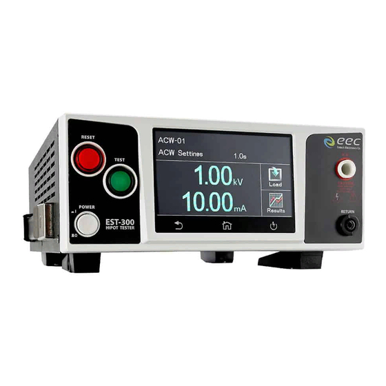
- Page 1 EST-300 Series EST-310/EST-320/EST-330 Electrical Safety Analyzer User Manual E1.05...
- Page 3 (2) year from date of shipment. During the warranty period, you must return the instrument to EEC or its branches or its authorized distributor for repair. EEC reserves the right to use its discretion on replacing the faulty parts or replacing the assembly or the whole unit.
-
Page 5: Table Of Contents
3.1 Specifications ......................14 3.2 Instrument Controls ....................17 3.2.1 EST-300 Series Front Panel Controls..............17 3.2.2 EST-300 Series Rear Panel Controls ..............18 4. Programming Instructions ................19 4.1 Using the Touch Screen ..................... 19 4.2 Main Menu ........................ 20 4.3 Setup System ...................... - Page 6 4.4 SCREEN LOCK......................28 4.5 FAILCHEK ........................28 4.5.1 AC Hipot FAILCHEK ..................... 29 4.5.2 DC Hipot FAILCHEK ..................... 30 4.5.3 IR FAILCHEK ......................30 4.6 Test Parameters ......................31 4.6.1 Description of Test Parameters ................31 4.6.2 Additional Parameter Notes and Functions ............32 4.7 Setup Tests .........................
-
Page 7: Introduction
1. Introduction 1.1 Safety Symbols 1.1.1 Product Marking Symbols Product will be marked with this symbol when it is necessary to refer to the operation and service manual in order to prevent injury or equipment damage. Product will be marked with this symbol when hazardous voltages may be present. Product will be marked with this symbol at connections that require earth grounding. -
Page 8: Glossary Of Terms
1.2 Glossary of Terms Alternating Current, AC: Current that reverses direction on a regular basis, commonly in the U.S.A. 60 per second, in other countries 50 times per second. Breakdown: The failure of insulation to effectively prevent the flow of current sometimes evidenced by arcing. -
Page 9: Safety
The instrument, its power cord, test leads, and accessories must be returned at least once a year to EEC customer support department for calibration and inspection of safety related components. EEC will not be held liable for injuries suffered if the instrument is not properly maintained and safety checked annually. -
Page 10: Test Operator
test station. Signs should be posted: "DANGER - HIGH VOLTAGE TEST IN PROGRESS - UNAUTHORIZED PERSONNEL KEEP AWAY." Work Area Perform the tests on a non-conducting table or workbench, if possible. If you cannot avoid using a conductive surface, be certain that it is connected to a good earth ground and the high voltage connection is insulated from the grounded surface. -
Page 11: Instrument Connections
will flow through any available ground path. Rules Operators should be thoroughly trained to follow all of the aforementioned rules, in addition to any other applicable safety rules and procedures. Defeating any safety system should be considered a serious offense with severe penalties such as removal from the Hipot testing job. Allowing unauthorized personnel in the area during a test should also be dealt with as a serious offense. -
Page 12: Key Safety Points To Remember
When testing with DC, always discharge the capacitance of the item under test and anything the high voltage may have contacted--such as test fixtures--before handling it or disconnecting the test leads. HOT STICK probes can be used to discharge any capacitance in the device under test as a further safety precaution. -
Page 13: The Different Types Of Safety Tests
1.5 The Different Types of Safety Tests 1.5.1 Dielectric Withstand Test The principle behind a dielectric voltage - withstand test is simple. If a product will function when exposed to extremely adverse conditions, it can be assumed that the product will function in normal operating circumstances. - Page 14 Types of Failures only detectable with a Hipot test Weak Insulating Materials Pinholes in Insulation Inadequate Spacing of Components Pinched Insulation Dielectric Withstand Test; AC verses DC Please check with the Compliance Agency you are working with to see which of the two types of voltages you are authorized to use.
- Page 15 AC testing disadvantages One disadvantage of AC testing surfaces when testing capacitive products. Again, since AC cannot charge the item under test, reactive current is constantly flowing. In many cases, the reactive component of the current can be much greater than the real component due to actual leakage. This can make it very difficult to detect products that have excessively high leakage current.
-
Page 16: Insulation Resistance Test
concerning exactly what equivalent DC test voltage is appropriate. 1.5.2 Insulation Resistance Test Some "dielectric analyzers today come with a built in insulation resistance tester. Typically, the IR function provides test voltages from 500 to 1,000 volts DC and resistance ranges from kilohms to gigaohms. -
Page 17: Key Features And Benefits
1.6 Key Features and Benefits Alerts the operator that the machine is due for CAL-ALERT calibration in advance of the calibration due date. SmartGFI™ disables the instrument’s output voltage in less than 1 millisecond if excessive leakage to ground is detected. If enabled, SmartGFI™ automatically PATENTED SMARTGFI... -
Page 18: Getting Started
If the shipping carton is damaged, inspect the contents for visible damage such as dents, scratches or broken display. If the instrument is damaged, notify the carrier and EEC's customer support department. Please save the shipping carton and packing material for the carriers inspection. Our customer support department will assist you in the repair or replacement of your instrument. -
Page 19: Power Requirements
2.2.2 Power Requirements This instrument requires a power source of either 100 - 120 volts AC ± 10%, 50/60 Hz single phase or 200 - 240 volts AC ± 10%, 50/60 Hz single phase. The instrument will autodetect the input voltage. -
Page 20: Specifications And Controls
3. Specifications and Controls 3.1 Specifications EST 310 EST 320 EST 330 Model EST-310 EST-320 EST-330 INPUT RATING Voltage (AC) 100 - 120Vac / 200 - 240Vac±10% Auto Range Apparent Power 360 VA Frequency 50/60 Hz ± 5% AC WITHSTAND VOLTAGE Output Rating 5KVAC / 20mA Output Voltage Range... - Page 21 ± (1% of setting + 0.5% of Voltage Meter Accuracy Range) Current Measurement Range 0.0 - 7500μA Current Resolution 0.1μA/0.001mA/0.01mA 0.0 - 400.0μA Current Accuracy 0.35 - 4.00 mA (1% of reading + 1% of Range) 3.50 - 7.50 mA Ramp Up Timer 0.1 - 999.9s Ramp Down Timer...
- Page 22 Charge-Lo Current 0.000 - 3.500 µA or Auto Set GENERAL Interface USB , PLC Remote Memory 30 steps (Maximum 30 Steps in one File) Display 4.3" Color Display (Touch Panel) Safety Built-in Smart GFI circuit, GFI trip current 450μA max Language English, T Chinese, S Chinese, Japanese Security...
-
Page 23: Instrument Controls
3.2 Instrument Controls 3.2.1 EST-300 Series Front Panel Controls POWER SWITCH: Powers the test instrument ON or OFF. RESET BUTTON: Resets the instrument. If a failure condition occurs during a test, pressing this button will reset the system, shut off the alarm and clear the failure condition. The Reset button must be pressed before performing another test or changing any of the setup parameters. -
Page 24: Est-300 Series Rear Panel Controls
3.2.2 EST-300 Series Rear Panel Controls CALIBRATION BUTTON: To put the instrument into the calibration mode push this button and turn on the power switch simultaneously. BUS INTERFACE: USB interface may be substituted for the RS-232. REMOTE SIGNAL OUTPUT: 9-Pin D sub-miniature female connector for monitoring PASS, FAIL, and PROCESSING output relay signals. -
Page 25: Programming Instructions
4. Programming Instructions 4.1 Using the Touch Screen The touch screen display of the EST-300 provides full control of the instrument. The touch screen will be used to setup system and test parameters as well as security setup and calibration. EST- 300’s touch screen functions just like any other touch screen. -
Page 26: Main Menu
Touch The various screens of the EST-300 will display icons and parameters. Touch the appropriate icon or parameter with the fingertip as shown in the image below: Scroll and Swipe A scroll bar on the right side of the screen indicates that there are additional parameters or features. -
Page 27: Setup System
Setup System – instrument global parameters such as time and date, calibration and hardware. Perform Tests – navigate to the Perform Tests screen in order to run a test sequence. Screen Lock – Lock the touch screen . Setup Tests – create test files FAIL-CHEK –... -
Page 28: Calibration Alert
move to the next field. The < (back arrow) key can be used to toggle between date, month and year. The Prev and Next arrows can be used to toggle between different fields under the Time and Date menu. 4.3.1.2 Set Time Use the touchscreen numeric keypad to enter the desired value for the hour, minute and second. -
Page 29: Hardware
Touch the desired value and the enter key ( ↵) will appear. Press the enter key to save the value and move to the next parameter under the Calibration Alert menu. The Prev and Next arrows can be used to toggle between different fields under the Calibration Alert menu. 4.3.2.1 Calibration Due Date and Alert Date It is recommended that calibration should be performed at least once a year. - Page 30 4.3.3.1 Smart GFI The high voltage power supply of the EST-300 is internally referenced to earth ground. Since the leakage current measuring circuit of the instrument monitors only current that flows through the return lead the possibility exists for current to flow directly from the high voltage output to earth ground without being measured.
-
Page 31: User Interface
The Single Step function can be set to ON or OFF. To set the Single Step, touch the ON/OFF key. To save the setting touch the enter key ( ↵) and move to the next parameter. 4.3.3.4 Fail Stop Fail Stop is a function that will stop a sequence if a failure occurs. If this function is turned off, the sequence of tests will continue to the end of the sequence regardless of whether or not a failure has occurred. - Page 32 When Last is selected, the results of the last step performed will be displayed on the Perform Tests screen. There will not be a change in appearance or special screen displayed in this mode: When P/F is selected, a Pass or Fail screen will be displayed at the end of the test. The Pass and Fail screens will appear as follows: Touch the screen to select the desired value and the enter key ( to save the selection and move...
-
Page 33: Information
off, and 9 being the loudest setting. Upon selecting a value, a momentary alarm chirp will occur to indicate the volume of the new setting, and the enter key ( will appear. Touch the enter key to save the value and move to the ↵) next field. -
Page 34: Screen Lock
4.4 SCREEN LOCK From the Main Menu select Screen Lock and the following screen will appear: The first option under Screen Lock allows the user to set ON or OFF. Screen Lock using the touchscreen keypad and choose between ON or OFF. The next option under Screen Lock is Set Password. -
Page 35: Ac Hipot Failchek
Select the FAILCHEK icon from the main menu and the following screen will appear: 4.5.1 AC Hipot FAILCHEK To perform an AC Hipot FAILCHEK, touch the AC Hipot icon and the following screen will appear: Follow the instructions on the screen. Press the Test button on the front panel of the instrument to start the test. -
Page 36: Dc Hipot Failchek
4.5.2 DC Hipot FAILCHEK To perform a DC Hipot FAILCHEK, touch the DC Hipot icon and the following screen will appear: Follow the instructions on the screen. Press the Test button on the front panel of the instrument to start the test. If the FAILCHEK test passes, the following screen will appear: If the FAILCHEK test fails, the following screen will appear: 4.5.3 IR FAILCHEK To perform an IR FAILCHEK, touch the IR icon and the following screen will appear:... -
Page 37: Test Parameters
Follow the instructions on the screen. Press the Test button on the front panel of the instrument to start the test. If the FAILCHEK test passes, the following screen will appear: If the FAILCHEK test fails, the following screen will appear: 4.6 Test Parameters This section details the various test parameter descriptions. -
Page 38: Additional Parameter Notes And Functions
Voltage: The voltage that is applied to the high voltage and return terminals during a test. Max Lmt: The maximum current or resistance threshold that triggers a failure when exceeded. Min Lmt: The minimum current or resistance threshold that triggers a failure when not exceeded. Ramp Up: The length of time that is allowed for the test voltage to climb from 0 to the programmed test voltage. -
Page 39: Setup Tests
The instrument can set the Charge-LO parameter manually or automatically. To manually set the Charge-LO current, use the up and down arrow keys or the ENTER key and scroll the highlighted area to the Charge-LO current parameter. Enter the new Charge-LO current via the numeric keypad and then press the ENTER key to accept the new parameter or press the EXIT key to escape from the edit. -
Page 40: Acw
Touch the Add Step icon to enter the test parameters screen. In this screen, the test type is selected and all the relevant test parameters are programmed and saved: Touch the add Bar icon to enter the barcode number. When you scan the barcode number the same as this parameter that the instrument will recall the test file. -
Page 41: View Test Files
Note: Charge-Lo: The parameter can be set automatically or manually. To perform an auto Charge- Lo, connect the DUT and all the test leads as needed to perform a real test. Press the test button on the front panel. Reading will be displayed on the screen when the instrument is performing the auto Charge-Lo. -
Page 42: Edit Test Files
For example: 4.7.5 Edit Test Files Once multiple test files have been programmed and saved the user can edit these files from the Setup Test menu. From the main menu select Setup Test. 4.8 PERFORM TESTS From the main menu select the Perform Test icon and the following screen will appear: This screen will display the first test that was saved in the test file. - Page 43 The user can select the desired test file and the first test step in the selected test file will be displayed. Meters The Perform Test screen of the EST-300 has several different meters depending on the type of test being performed. These meters can be arranged as desired by the user and can also be tied to the user security setup.
- Page 44 Results Last Smart GFI Results Last Cal Alert...
-
Page 45: Test Connections
5. Test Connections 5.1 Connecting the Test Leads The instrument comes with all cables necessary for performing a Hipot and Continuity test. Plug the red alligator clip into the HV receptacle on the instrument. Connect one of two black alligator clip leads to the Return receptacle and the other to the Cont. -
Page 46: Results Screens
6. Results Screens After a test has completed the Results icon will be available on the screen. For example: Select the Results icon to enter the results screen. The Results screen will appear as follows: The Results screen allows you to view the results of the last test step the instrument performed and the results of the previously performed tests. -
Page 47: Error Messages And Fail Messages
Scroll down to view all the test results: Touch and hold any test step result on the previous screen and a new screen will pop up: 6.1 Error Messages and Fail Messages If there is an error during testing, the error description will be displayed on the screen. Below is a list of error messages that the EST-300 reports: Abort: This message appears on the display if the test in process is aborted with the RESET button or remote Reset control. - Page 48 Perform Test screen. Fatal Error: If the instrument has a Fatal Error failure then the following screen will appear: All of the buttons and keys are not active in this situation. You should contact EEC to receive further instruction. Fatal Error identification number will represent type of the failure that occurs.
-
Page 49: Connection Of Remote I/O
7. Connection of Remote I/O Two 9-pin “D” type connectors mounted on the rear panel provide REMOTE-INPUT-OUTPUT control and information. These connectors mate with a standard 9 pin D-sub-miniature connector provided by the user. The output mates to a male (plug) connector while the input mates to a female (receptacle) connector. -
Page 50: Remote Signal Inputs And Memory Access
reset function is activated. FAIL – The relay contact closes the connection between pin (3) and pin (4) after detecting that the item under test failed. The connection will open when the next test is initiated or the reset function activated. 7.2 Remote Signal Inputs and Memory Access The EST-300 remote connector enables remote operation of the TEST, RESET, and REMOTE INTERLOCK functions, and allows the operator to select one of 3 pre-programmed test files. -
Page 51: Bus Remote Interface Usb
8. Bus Remote Interface USB This section provides information on the proper use and configuration of bus remote interface. The USB remote interface is standard on EST-300 series. The USB communication speed of the EST-300 is 38400 baud. 8.1 USB Interface Command List... -
Page 52: File Editing Commands
Set the Charge-LO parameter for the DCW or IR test. The cables and any test fixture should be connected before executing the command. The test parameters that are set for the step will be used when performing the auto setting. This command will perform an actual test and all safety precautions should be observed when using this command. -
Page 53: Test Parameter Editing Commands And Companion Queries
SS <step number> Selects the active selected step to load into RAM. The step must first be selected before any specific parameters can be edited. SAA, SAD, SAI, SAG, SAC These commands add the appropriate test type within the memory at the step location that has been selected. -
Page 54: System Parameter Editing Commands And Companion Queries
therefore used a different possible set of values. Command Name Test Value Types EV <value> Edit Voltage 10 - 5000V 10 - 6000V 10 - 1000V ECG < value > Edit Charge-Lo 0.0 - 350.0uA ECG? 0.000 - 3.500uA ERU < value> Edit Ramp-Up - 999.9s ERU? - Page 55 Command Name Value RD nn? nn=1 - 30 Read the result of testing step Query the maximum current test RDM? results 0=CLOSE Query the status of RESET 1=OPEN 0=CLOSE Query the status of INTERLOCK 1=OPEN SSG n n=0, 1 Set the Smart GFI SSG? Query the status of Smart GFI SPR n...
-
Page 56: Status Reporting
Command Name Value SDT? Date Format by SDF Query the date n=0 - 2 0=ymd SDF n Set the form of date 1=mdy 2=dmy SDF? Query the form of date STM hh,mm Time Format by STF Set the time STM? Time Format by STF Query the time n=0 - 1,... - Page 57 automatically clears the register and sets all bits to inactive state or 0. When querying an Event register the information is returned as a decimal number representing the binary-weighted sum of all bits within the register. The Enable registers bits represent the selection of bits that will be logically OR’d together to form the summary bit in the Status Byte.
-
Page 58: Calibration
EEC offers a standard one-year manufacture’s warranty. This warranty can be extended an additional four years provided that the instrument is returned each year to EEC for it’s annual calibration. In order to be eligible for the extended warranty instruments must be returned to EEC for calibration service at least once every twelve months. -
Page 59: Calibration Initialization
9.2 Calibration Initialization Press and hold the calibration key on the rear panel with a pen, pencil, or small screwdriver while powering ON the EST-300. The EST-300 enters calibration mode after the power on sequence is complete. When the calibration is initialized the calibration screen will display each calibration point and appear as follows: Scroll down on the screen to view the next page which will appear as follows: 9.3 Calibration of Parameters... - Page 60 Calibration of DC Hipot Voltage Connect the standard 6KVDC kilovolt meter from H.V. to Return. When the standard voltmeter is connected, press TEST to start the calibration process. Enter Standard Voltage Reading. Calibration of 20mA AC Total Current Range Connect the 100K...
- Page 61 Calibration of 350nA DC Current Range Connect the 1G load in series with the standard current meter. When the load is connected, press TEST to start the calibration process. Enter Standard Current Reading. Calibration Date 11/05/2014 Enter the date of Calibration.
Need help?
Do you have a question about the EST-300 Series and is the answer not in the manual?
Questions and answers