
Related Manuals for IDS GigE uEye SE Rev. 4

Summary of Contents for IDS GigE uEye SE Rev. 4
- Page 1 GigE uEye SE Rev. 4 Technical Manual IDS Imaging Development Systems GmbH Dimbacher Str. 6-8 D-74182 Obersulm, Germany T: +49 7134 96196-0 E: info@ids-imaging.com W: https://de.ids-imaging.com...
-
Page 2: Table Of Contents
5 GigE uEye SE Rev. 4 ......................... 8 5.1 Ambient conditions ........................8 5.2 System requirements ......................... 10 5.3 Connecting a GigE uEye SE Rev. 4 .................... 10 6 Mechanical specifications ........................ 11 7 Notes on PCB version ........................12 8 Optical specifications ........................ -
Page 3: Preface
Please contact your local IDS distributors for first level support in your language. For a list of IDS distributors worldwide please go to our website https://de.ids-imaging.com. -
Page 4: Symbols And Hints
Technical Manual: GigE uEye SE Rev. 4 2 Symbols and hints This symbol indicates hints with useful information for better understanding and using features and functions. This symbol indicates important warnings for product safety to prevent damage. This symbol indicates important warnings for personal safety to prevent injury. -
Page 5: Safety Instructions
All warranty will be spoiled in this case. Intended use IDS industrial cameras are to be used to capture images for visualization and image processing tasks. They are designed for use in industrial environments. Please comply with the requirements for the proper use of this product. - Page 6 Technical Manual: GigE uEye SE Rev. 4 Operation and power supply The camera power supply must meet the requirements for SELV (safety extra low voltage)/LPS (limited power source) or ES1/PS2. WARNING! Non-approved power supplies for camera operation may cause painful or dangerous electric shock.
-
Page 7: Standards And Directives
Technical Manual: GigE uEye SE Rev. 4 4 Standards and directives (only valid for devices with housing) IDS Imaging Development Systems GmbH hereby confirms that this product has been developed, designed and manufactured in compliance with the following European directives ·... -
Page 8: Gige Ueye Se Rev. 4
55 °C (131 °F). Notes on ambient conditions · Avoid high air humidity levels and rapid temperature changes when using IDS cameras. · Temperatures below +4 °C (39 °F) combined with excessive relative air humidity levels can cause icing. - Page 9 Technical Manual: GigE uEye SE Rev. 4 · If necessary, provide an active cooling for example by means of a fan. With increasing device temperatures, the image quality could be reduced due to thermal noise. It is recommended to mount the camera to a heat-dissipating unit even if the camera is operated below the maximum specified temperature.
-
Page 10: System Requirements
Depending on the sensor model, the camera performance may be limited with the minimum system requirements. 5.3 Connecting a GigE uEye SE Rev. 4 Check the power supply to the camera. Connect the camera to to a Gigabit Ethernet port on the PC either directly or using switches. -
Page 11: Mechanical Specifications
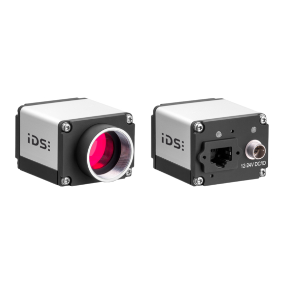
Technical Manual: GigE uEye SE Rev. 4 6 Mechanical specifications The mechanical data for each camera model can be found on our website directly at the respective camera model beneath in the "Downloads" tab. Fig. 1: GigE uEye SE Rev. 4 NOTICE! The camera connectors may be damaged if you install or remove the camera with plugged in cables. -
Page 12: Notes On Pcb Version
Mounting details The GigE uEye SE Rev. 4 cameras can be mounted either using the two holes on the bottom of the front panel or via the four holes on the front. Connecting the front panel to the camera shield is only possible with the two variants displayed. - Page 13 Technical Manual: GigE uEye SE Rev. 4 For versions without front panel, two screws can be used to mount the PCB stack from the backside. The following figure shows the mounting with S-board. To do this, remove first the transport lock (two nuts and safety plate).
- Page 14 Technical Manual: GigE uEye SE Rev. 4 Fig. 7: ESD protection January 2020...
-
Page 15: Optical Specifications
Technical Manual: GigE uEye SE Rev. 4 8 Optical specifications · Immersion depth for lenses · Position accuracy of the sensor 8.1 Immersion depth for lenses Some C-mount lenses reach deep into the camera flange. This may cause the lens to push against the back of the filter glass inside the camera or even make it impossible to screw in the lens. -
Page 16: Position Accuracy Of The Sensor
Technical Manual: GigE uEye SE Rev. 4 8.2 Position accuracy of the sensor The following illustrations show the tolerance margins of the sensor position relative to the outer camera housing. A maximum error in all directions (rotation, translation) cannot occur at the same time. -
Page 17: Electrical Specifications
Bl_DC- rear view Bl_DB- Bl_DD+ Bl_DD- The RJ45 socket of the GigE uEye SE Rev. 4 complies with the IEC 60603-7 standard. 9.2 Pin assignment I/O connector 8-pin Hirose connector (HR25-7TR-8PA(73)) Description Ground (GND) Flash output with optocoupler (-) General Purpose I/O (GPIO) 1, 3.1 V... -
Page 18: Digital Input Wiring
12 V. To supply the GigE uEye SE Rev. 4 camera with power using PoE or PoE+, you can use PoE injectors or switches that are compatible with IEEE standard 802.3af or IEEE standard 802.at. -
Page 19: Digital Output Wiring
Technical Manual: GigE uEye SE Rev. 4 Digital input wiring Fig. 13: Wiring of the trigger connector 9.4 Digital output wiring Symbol Min. Typ. Max. Unit Recommended supply voltage Collector-emitter saturation voltage 0.03 0.15 CE(SAT) Collector-emitter breakdown voltage (BR)CE Collector current continuous The digital output is galvanically isolated using an optocoupler to protect the camera and the PC against surges. - Page 20 Technical Manual: GigE uEye SE Rev. 4 Fig. 14: Wiring of the digital output as an open collector output Fig. 15: Wiring of the digital output as an open emitter output January 2020...
-
Page 21: General Purpose I/O Wiring
Technical Manual: GigE uEye SE Rev. 4 9.5 General Purpose I/O wiring The two programmable GPIOs (general purpose I/O) can be used as inputs or outputs. This selection is made by software using the corresponding functions. Please observe the following criteria: Symbol Min. - Page 22 Technical Manual: GigE uEye SE Rev. 4 GPIO wiring as output Fig. 17: GPIO wiring as output (1) Fig. 18: GPIO wiring as output (2) January 2020...
-
Page 23: Status Led
Technical Manual: GigE uEye SE Rev. 4 10 Status LED Fig. 19: Status LEDs The camera has two LEDs that indicate information of the current status. · LED 1: camera status (two-color) · LED 2: Network status (two-color) LED 1... -
Page 24: Filter Glasses
Every camera model is available with different filter variants such as daylight cut filters (type DL). The filter type is given at the end of the model name. The following table shows an overview of the different optical filters used in IDS cameras: Refractive... -
Page 25: Cleaning The Filter Glasses
The filter glasses may only be cleaned from the outside. If you remove the glasses, the sensor might get soiled.IDS Imaging Development Systems GmbH is not liable for any damage to the sensor resulting from removal of the filter glasses. - Page 26 Technical Manual: GigE uEye SE Rev. 4 use purified nitrogen from nitrogen bottles. · Only use lint-free wipes or cotton-free swabs for cleaning. Never touch the filter glasses with your bare fingers because often, fingerprints cannot be removed completely afterwards.
-
Page 27: Index
Technical Manual: GigE uEye SE Rev. 4 Windows - A - Output Ambient conditions digital - C - - P - Contact Pin assignment Plain glass filter - D - - R - Daylight cut filter Dimensions RJ45 - E -...
Need help?
Do you have a question about the GigE uEye SE Rev. 4 and is the answer not in the manual?
Questions and answers