Advertisement
Quick Links
TM
F E NI E X / /
2 019
/ /
I NSTR U CTI ON MANUAL
WE B / / w w w.fe ni ex i ndu s t r i es .com
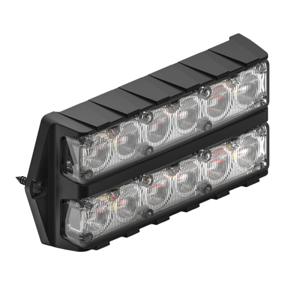
FDSM-40
FDSM-180
FUSION DUAL STACK
INSTRUCTION MANUAL
Feniex Product Copyrights This price List and the mentioned Feniex products include or describe copyrighted Feniex material. Laws in the United States and other countries
preserve for Feniex Industries and its licensors certain exclusive rights for copyrighted material, including the exclusive right to copy, reproduce in any form, distribute and make
derivative works of the copyrighted material. Accordingly, any copyrighted material of Feniex and its licensors contained herein or in the Feniex products described in this Price
List may not be copied, reproduced, distributed, merged or modified, transmitted, transcribed, stored in retrieval system or translated into any language or computer language,
in any form or by any means, without prior written permission of Feniex Industries, Inc.. Feniex and the stylized Feniex logo are registered in the U.S. Patent & Trademark Office.
Advertisement

Related Manuals for Feniex Fusion FDSM-40


Summary of Contents for Feniex Fusion FDSM-40
- Page 1 List may not be copied, reproduced, distributed, merged or modified, transmitted, transcribed, stored in retrieval system or translated into any language or computer language, in any form or by any means, without prior written permission of Feniex Industries, Inc.. Feniex and the stylized Feniex logo are registered in the U.S. Patent & Trademark Office.
- Page 2 TABLE OF CONTENTS Safety Regulations & Warranty Service after Expiration Copyright Feniex Product Copyright Specifications & Flash Patterns Box Contents Flash Patterns Specifications Dimensions Wiring & Configuration Wiring Diagram Setting Master/Slave Patterns & Synchronization FE NI E X // 20 19 / / I NST R UCT I ON MAN UAL / / v 1.
-
Page 3: Safety Regulations & Warranty
SAFETY REGULATIONS CONDITIONS The following provides all the information necessary to Feniex Industries, Inc. will not be held responsible for any safely operate the previously listed products of Feniex costs associated with equipment removal and/or Industries, Inc. Please read this manual thoroughly before re-installation resulting from a warranty claim. - Page 4 SPECIFICATIONS, BOX CONTENTS & FLASH PATTERNS FLASH PATTERNS: SINGLE COLOR BOX CONTENTS 1. Single Slow 7. Triple Slow Fusion Surface Mount 2. Single Fast 8. Triple Fast Bezel 3. Single Combo 9. Triple Combo Screws 4. Double Slow 10. Brake Pop Protective Pad 5.
-
Page 5: Wiring Diagram & Instructions
WIRING DIAGRAM & INSTRUCTIONS WIRING DIAGRAM WIRING DIAGRAM AND INSTRUCTIONS: 1. To activate the unit, extend the red (+) or yellow (+) wire COLOR FUNCTION POLARITY CONNECTION to a 12V post. Extend the black (-) wire to the ground post Mode 1 12v (+) Latching Switch...
Need help?
Do you have a question about the Fusion FDSM-40 and is the answer not in the manual?
Questions and answers