
Subscribe to Our Youtube Channel
Related Manuals for BIRD Termaline 8400 Series

Summary of Contents for BIRD Termaline 8400 Series
- Page 1 ® Termaline Coaxial Load Resistor 8400 Series Operation Manual ©Copyright 2016 by Bird Technologies, Inc. Instruction Book P/N 920-8400S Rev. A ® Termaline is a Registered Trademark of Bird Electronic Corporation...
-
Page 2: Safety Precautions
Safety Precautions The following are general safety precautions that are not necessarily related to any specific part or procedure, and do not necessarily appear elsewhere in this publication. These precautions must be thoroughly understood and apply to all phases of operation and maintenance. WARNING Keep Away From Live Circuits Operating Personnel must at all times observe general safety precautions. -
Page 3: Safety Symbols
Safety Precautions Safety Symbols WARNING Warning notes call attention to a procedure which, if not correctly performed, could result in personal injury. CAUTION Caution notes call attention to a procedure which, if not correctly performed, could result in damage to the instrument. The caution symbol appears on the equipment indicating there is important information in the instruction manual regarding that particular area. -
Page 4: Caution Statements
Termaline® Coaxial Load Resistor Caution Statements The following cautions appear in the text whenever the equipment is in danger of damage, and are repeated here for emphasis. CAUTION The load is designed for operation in a horizontal plane only, with mounting brackets down. -
Page 5: Safety Statements
Safety Precautions Safety Statements USAGE ANY USE OF THIS INSTRUMENT IN A MANNER NOT SPECIFIED BY THE MANUFACTURER MAY IMPAIR THE INSTRUMENT’S SAFETY PROTECTION. EL USO DE ESTE INSTRUMENTO DE MANERA NO ESPECIFICADA POR EL FABRICANTE, PUEDE ANULAR LA PROTECCIÓN DE SEGURIDAD DEL INSTRUMENTO. - Page 6 Termaline® Coaxial Load Resistor SERVICE SERVICING INSTRUCTIONS ARE FOR USE BY SERVICE - TRAINED PERSONNEL ONLY. TO AVOID DANGEROUS ELECTRIC SHOCK, DO NOT PERFORM ANY SERVICING UNLESS QUALIFIED TO DO SO. SERVICIO LAS INSTRUCCIONES DE SERVICIO SON PARA USO EXCLUSIVO DEL PERSONAL DE SERVICIO CAPACITADO.
-
Page 7: About This Manual
About This Manual About This Manual This instruction book covers the following models of Termaline Load Resistors. 8401 8404 Changes To The Manual We have made every effort to ensure this manual is accurate at the time of publication. If you should discover any errors or if you have suggestions for improving this manual, please send your comment to our factory. -
Page 8: Table Of Contents
Table of Contents Safety Precautions ......... i Safety Symbols . - Page 9 Table of Contents Normal Operation ..........6 Operating Under Emergency, Adverse, or Abnormal Conditions .
-
Page 10: Chapter 1 Introduction
Chapter 1 Introduction This publication refers to the Termaline Load Resistor models 8401 and 8404. The differences between the models are listed in the specifications. Both models will generally be referred to as a load throughout this manual. Purpose and Function These loads are portable, general purpose 50 ohm coaxial transmission line terminations. -
Page 11: Dimensions And Weight
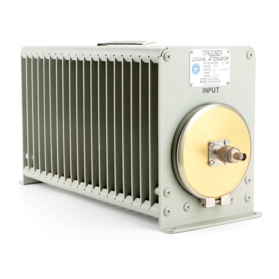
Introduction Dimensions and Weight The loads are 16-1/16 inches L x 5-15/16 inches W x 8-1/2 inches H (408 x 151 x 216 mm). They have a net weight of 19.6 lb (8.9 kg) and a shipping weight of approximately 25 lb (11.34 kg). Power and Utility Requirements These load resistors are passive devices that are self contained and do not require a source of power or utility service to perform their function, other than... - Page 12 Termaline® Coaxial Load Resistor An ohmmeter with an accuracy of 1 percent or better at 50 ohms is recommended for checking the resistance value of the resistor. Figure 1 Model 8401...
-
Page 13: Chapter 2 Theory Of Operation
Chapter 2 Theory of Operation The Termaline Load Resistors consist essentially of a carbon film-on-ceramic resistor immersed in a dielectric coolant. The resistor, individually selected for its accuracy, is enclosed in a special exponentially tapered housing. This provides a linear reduction in surge impedance directly proportional to the distance along the resistor. -
Page 14: Chapter 3 Installation
Chapter 3 Installation Location CAUTION The load is designed for operation in a horizontal plane only, with mounting brackets down. Do not operate in any other position. Install the Termaline Load Resistor in a location that: Has sufficient room to provide at least 12 inches (304.8 mm) of free space around and above the unit. -
Page 15: Chapter 4 Operating Instructions
Chapter 4 Operating Instructions Use and Function of Controls Because these are passive devices, there are no operating controls on the Load Resistors. Initial Adjustments No initial adjustments are required other than to connect the load to the RF source by means of a coaxial cable equipped with a suitable matching connector plug. -
Page 16: Operating Under Emergency, Adverse, Or Abnormal Conditions
Termaline® Coaxial Load Resistor Operating Under Emergency, Adverse, or Abnormal Conditions CAUTION Do not operate this equipment continuously above the rated 600 W. Load failure will result. Shutdown Because the loads are passive devices, there is no way to turn them off. Power must be shut off at the source of the RF energy. -
Page 17: Chapter 5 Maintenance
Chapter 5 Maintenance This chapter contains operator maintenance instructions, troubleshooting, and parts information. Troubleshooting Problem Possible Cause Remedy Tighten clamping band with Clamping band not tight. a screwdriver. Leakage of coolant oil Replace per the RF Load around band or radiator Faulty o-ring (front). -
Page 18: Inspection
Termaline® Coaxial Load Resistor Inspection With the rugged and simple construction of the Load Resistors, periodic inspection will be necessary at only about six-month intervals. Inspection should include the items listed below: 1. Oil Leakage - Check for coolant oil seepage around the radiator tank, particularly at the front and back around the underside of the clamping band. -
Page 19: Rf Connector Replacement
Maintenance RF Connector Replacement The connector is a patented “Quick Change” design which permits easy interchange with the use of only a screwdriver. This process does not interfere with the essential coaxial continuity of the load resistor RF input or the coolant oil seal. -
Page 20: Assembly
Termaline® Coaxial Load Resistor Assembly RF Connector Before pushing the RF connector in, be sure that the projecting center contact pin on the connector is carefully engaged and properly seated in the mating socket of the load resistor input. Install the four 8-32 x 5/16 inch round head machine screws into the corners of the RF connector. -
Page 21: Repairs
If the unit needs to be returned for any reason, request an Return Material Authorization (RMA) through the Bird Technologies website. All instruments returned must be shipped prepaid and to the attention of the RMA number. -
Page 22: Specifications
Termaline® Coaxial Load Resistor Specifications Impedance, Nominal 50 ohms VSWR, Max DC-1000 MHz 1.1:1.0 1000-2800 MHz 1.2:1.0 2800-3000 MHz 1.3:1.0 Connectors Female N “QC” type normally supplied 8401 Female N “QC” type normally supplied, 8401 plus UG-57G/U N(M) to N(M) adapter and dust cap Power Range 600 W Continuous... -
Page 23: Replacement Parts List
Maintenance Replacement Parts List Item Qty. Description Part Number Radiator assembly 2440-001-1 RF Section assembly 8401-002 .7 Gal 5-030-3 Dielectric coolant (2.65 liters) (1 Gallon) “QC” connector *see below Diaphragm 2430-015 Diaphragm cover 2430-148 Clamp band (includes 10-32 x 1- 2430-055 1/2”... -
Page 24: Limited Warranty
Limited Warranty All products manufactured by Seller are warranted to be free from defects in material and workmanship for a period of one (1) year, unless otherwise specified, from date of shipment and to conform to applicable specifications, drawings, blueprints and/or samples. Seller’s sole obligation under these warranties shall be to issue credit, repair or replace any item or part thereof which is proved to be other than as warranted;...
Need help?
Do you have a question about the Termaline 8400 Series and is the answer not in the manual?
Questions and answers