
Related Manuals for Blue Wave FX 48SM Series


Summary of Contents for Blue Wave FX 48SM Series
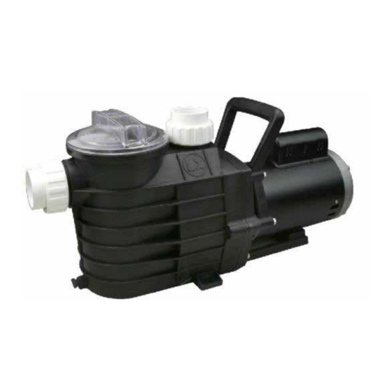
- Page 1 48SMⅠ, 48SM Ⅱ SWIMMING POOL PUMPS INSTRUCTION MANUAL NE4491/4492/4493/4494 VER.0418 NE4495/4496/4497/4498...
-
Page 2: Important - Read Carefully
IMPORTANT – READ CAREFULLY NOTE – To prevent potential injury and to avoid unnecessary service calls, read this manual carefully and completely. SAVE THIS INSTRUCTION MANUAL Use of unauthorized replacement parts voids warranty. ATTENTION INSTALLER – THIS MANUAL CONTAINS IMPORTANT INFORMATION ABOUT THE INSTALLATION, OPERATION, AND SAFE USE OF THIS PUMP THAT MUST BE FURNISHED TO THE END USER OF THIS PRODUCT. - Page 3 Locate cord to prevent abuse from lawn mowers, hedge trimmers and other equipment. WARNING – Connect only to a grounding type receptacle protected by a Ground Fault Circuit Interrupter (GFCI). Contact a licensed electrician if you cannot verify that the receptacle is protected by a GFCI. WARNING –...
- Page 4 - In addition to two or more suction outlets per pump installed in accordance with latest IAF (formerly NSPI) standards and CPSC guidelines, follow all national, state, and local codes applicable. - Installation of a vacuum release or vent system, which relieves entrapping suction, is recommended. WARNING –...
-
Page 5: Installation Instructions
Installation Instructions WARNING – This product should be installed and serviced only by a qualified professional. Pump Location Locate pump as close to pool as practical and run suction lines as direct as possible to reduce friction loss. Suction lines should have continuous slope upward from lowest point in line. Joints must be tight (but not over-tightened). Suction line diameter must equal or be larger than the discharge line diameter. - Page 6 necessary to tighten fittings enough to prevent leakage. Tighten fitting by hand and then use a tool to engage fitting an additional 1 ½ turns. Use care when using Teflon tape as friction is reduced considerably; Do NOT over-tighten fitting or you may cause damage. If leaks occur, remove fitting, clean off old Teflon tape, re-wrap with one to two additional layers of Teflon tape, and re-install fitting.
-
Page 7: Start-Up And Operation
Voltage Voltage at motor MUST NOT be more than 10% above or below motor name plate rated voltage, or motor may overheat, causing overload tripping and reduced component life. If voltage is less than 90% or more than 110% of rated voltage when motor is running at full load, consult Power Company. -
Page 8: Maintenance
Fill strainer housing with water to suction pipe level. NEVER OPERATE THE PUMP WITHOUT WATER. Water acts as a coolant and lubricant for the mechanical shaft seal. WARNING – If pump is being pressure tested (40 PSI MAXIMUM), be sure pressure has been released, using the filter manual air relief valve, before removing strainer cover. -
Page 9: Storing Pump For Winterization
replace as necessary. Pumps have self-lubricating motor bearings and shaft seals. No lubrication is necessary. Keep motor clean. Insure air vents are free from obstruction to avoid damage. Do NOT use water to hose off motor. Occasionally, shaft seals must be replaced, due to wear or damage. Replace with genuine seal assembly kit. See “Shaft Seal Change Instructions”... -
Page 10: Troubleshooting
B. Disconnect all electrical power service to pump before beginning shaft seal replacement. C. Only qualified personnel should attempt rotary seal replacement. Contact your local authorized Dealer or service center if you have any questions. D. Exercise extreme care in handling both the rotating and the stationary sections of the two-part replacement seal. Foreign matter or improper handling will easily scratch the graphite and ceramic sealing surfaces. - Page 11 Solution: Tighten, repair, or replace valves. 4. Strainer basket or skimmer basket loaded with debris. Solution: Remove strainer housing cover or skimmer cover, clean basket, and refill strainer housing with water. Tighten cover. 5. Suction side clogged. Solution: Contact a qualified repair professional. Block off to determine if pump will develop a vacuum.
- Page 12 4. Motor bearings noisy from normal wear, rust, overheating, or concentration of chemicals causing seal damage which will allow chlorinated water to seep into bearings wiping out the grease causing bearing to whine. Solution: All seal leaks should be replaced at once. Installation Circuit Diagram As the colours of the wires in the mains lead of this appliance may not correspond with the coloured markings identifying the terminals in your connection unit proceed as follows.
-
Page 13: Performance Curves
Performance Curves U .S .G P M IMP.G P M (ft) (psi) 3450r/min 1725r/min l/min m /h Flow Installation Structure 2F B T page 13... - Page 14 Mode l Powe r Qm a x Hm a x Cu rve s V/Hz Am p s (l/ m in) (m ) BW Model Factory Model 48SM0753C-I 10/5 0.55 0.75 115/230 -60 12/6 NE4493 48SM1003C-I 17/8.5 1.25 1.65 1.85 NE4496 48SM1653C-I 230/6 0 NE4497...
- Page 15 FX 48SM SERIES PUMP PARTS BREAKDOWN Part Name Manf. No. B.W. No. TIE-IN NUT 48SM001 NEP4138 48SM002 NEP4139 O-RING 48SM003 NEP4140 PUMP CASING 48SM004 NEP4141 FILTER 48SM005 NEP4142 O-RING 48SM006 NEP4143 TRANSPARENT COVER 48SM007 NEP4144 O-RING NEP4145 48SM008 GUIDE PLATE...
- Page 16 FX 48SM SERIES PUMP PARTS DIAGRAM page 16...
Need help?
Do you have a question about the FX 48SM Series and is the answer not in the manual?
Questions and answers