Table of Contents
Advertisement
Quick Links
Page 1 of 16
INSTRUCTION MANUAL
LI-550C LINE IMPEDANCE STABILIZATION NETWORK
INSTRUCTION MANUAL
For
LINE IMPEDANCE STABILIZATION NETWORK
Model LI-550C
100 kHz to 108 MHz
1 9 1 2 1 E l T o r o R d ● S i l v e r a d o , C a l i f o r n i a 9 2 6 7 6 ● ( 9 4 9 ) 4 5 9 - 9 6 0 0 ● c o m - p o w e r . c o m
REV021317
Advertisement
Table of Contents

Related Manuals for Com-Power LI-550C


Summary of Contents for Com-Power LI-550C
- Page 1 Page 1 of 16 INSTRUCTION MANUAL LI-550C LINE IMPEDANCE STABILIZATION NETWORK INSTRUCTION MANUAL LINE IMPEDANCE STABILIZATION NETWORK Model LI-550C 100 kHz to 108 MHz 1 9 1 2 1 E l T o r o R d ● S i l v e r a d o , C a l i f o r n i a 9 2 6 7 6 ● ( 9 4 9 ) 4 5 9 - 9 6 0 0 ● c o m - p o w e r . c o m...
-
Page 2: Table Of Contents
Page 2 of 16 INSTRUCTION MANUAL LI-550C LINE IMPEDANCE STABILIZATION NETWORK Table of Contents Introduction .......................... 3 Products Available from Com-Power................4 Product Safety Information ....................5 3.1 Product Hazard Symbols Definitions ................. 5 3.2 Incoming Inspection ......................6 Package Inventory ......................6 General Safety Instructions ..................... -
Page 3: Introduction
Information contained in this manual is the property of Com-Power Corporation. It is issued with the understanding that the material may not be reproduced or copied without the express written permission of Com-Power. -
Page 4: Products Available From Com-Power
Page 4 of 16 INSTRUCTION MANUAL LI-550C LINE IMPEDANCE STABILIZATION NETWORK 2.0 P RODUCTS VAILABLE FROM OWER Coupling/Decoupling Antennas Antenna Kits Absorbing Clamps Networks (CDN) Conducted Immunity Emissions Test Comb Generators Current Probes Test Systems Systems Near-Field Impedance Stabilization Line Impedance Stabilization... -
Page 5: Product Safety Information
Page 5 of 16 INSTRUCTION MANUAL LI-550C LINE IMPEDANCE STABILIZATION NETWORK 3.0 P RODUCT AFETY NFORMATION 3.1 Product Hazard Symbols Definitions The hazard symbols appearing on the product exterior are defined below. The yellow triangle with an exclamation mark indicates the presence of important operating and/or maintenance (servicing) instructions in the literature accompanying the product. -
Page 6: Incoming Inspection
Please check the contents of the shipment against the package inventory in section 3.3 to ensure that you have received all applicable items. Package Inventory Equipment, accessories, and documents supplied with the model LI-550C LISN are as follows: Calibration data and Certificate traceable to NIST. - Page 7 CAUTION: The LI-550C is based on the 5 µH artificial mains network (AMN) circuit and component values (Figure E.2) specified in CISPR 25 – 2008-03 Vehicles, boats and internal combustion engines – Radio disturbance characteristics –...
- Page 8 Page 8 of 16 INSTRUCTION MANUAL LI-550C LINE IMPEDANCE STABILIZATION NETWORK • DEFECTS AND ABNORMAL STRESS - Whenever it is likely that the normal operation has been impaired, make the equipment inoperable and secure it against further operation. • SITTING OR CLIMBING - Do not sit or climb upon the instrument or use it as a step or ladder.
-
Page 9: Product Specifications
Page 9 of 16 INSTRUCTION MANUAL LI-550C LINE IMPEDANCE STABILIZATION NETWORK 4.0 P RODUCT PECIFICATIONS Model: LI-550C Electrical Frequency range: 150 kHz to 30 MHz Compliant standards: CISPR 25, CISPR 16-1-2 Edition 2.0: 2014- Number of lines: Two lines Max current rating:... -
Page 10: Product Description
CE and other worldwide standards for commercial products. It is fully compliant with the requirements of both CISPR 16-1-2 and CISPR 25. The LI-550C performs each of the following functions during the measurement: • provides a defined, stable impedance throughout the measurement frequency range;... -
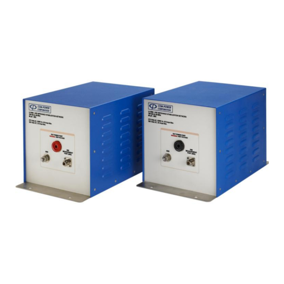
Page 11: Front & Rear Panel Marking
Figure 4: Front Panel 5.3.1 Power input port The Model LI-550C has a Superior Electric Shrouded pin receptacle for connection to an external DC or AC input power source. The LISN is shipped with two matching shrouded socket plug, for connection to the input power source cables. - Page 12 EUT power cable. 5.3.4 EMI measurement Port The LI-550C provides a 50 Ω N-Type (female) connector to connecting the Spectrum analyzer or EMI receiver for making conducted noise measurements. The shielding connection of the N connector shield is connected to the housing of the LISN and thus to ground.
-
Page 13: Lisn Theory
LISN with minimal attenuation. This filter is comprised of a single stage low pass LC filter. The inductors (L) used in the LI-550C are air core type to eliminate the possibility of saturation and to provide stability. -
Page 14: Typical Performance Data
Page 14 of 16 INSTRUCTION MANUAL LI-550C LINE IMPEDANCE STABILIZATION NETWORK 7.0 T YPICAL ERFORMANCE LISN Impedance CISPR 16-1-2, Ed.1.2, Tbl 5 (5uH) Impedance Limits (±20%) CISPR 25, Ed.3 (5uH) Impedance Limits (±20%) 1000 Frequency (MHz) Figure 6: Typical Impedance compared to CISPR 25 & CISPR 16-1-2 requirements LISN Phase CISPR 16-1-2, Ed.1.2, Tbl 5... - Page 15 Page 15 of 16 INSTRUCTION MANUAL LI-550C LINE IMPEDANCE STABILIZATION NETWORK LISN Isolation CISPR 16-1-2 Edition 1.2 (Isolation Limit - Minimum) 1000 Frequency (MHz) Figure 8: Typical Isolation compared to CISPR 16-1-2 requirements LISN Insertion Loss 1000 Frequency (MHz) Figure 9: Typical Insertion Loss 1 9 1 2 1 E l T o r o R d ●...
-
Page 16: Warranty
LI-550C LINE IMPEDANCE STABILIZATION NETWORK 8.0 W ARRANTY Com-Power warrants to its Customers that the products it manufactures will be free from defects in materials and workmanship for a period of three (3) years. This warranty shall not apply to: ...
Need help?
Do you have a question about the LI-550C and is the answer not in the manual?
Questions and answers