Table of Contents
Advertisement
Quick Links
Page 1 of 24
INSTRUCTION MANUAL
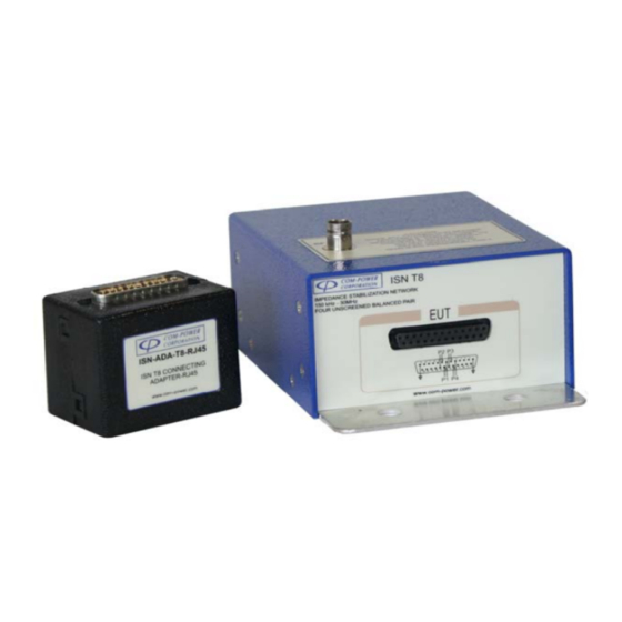
ISN T8 IMPEDANCE STABILIZATION NETWORK (ISN)
INSTRUCTION MANUAL
for
IMPEDANCE STABILIZATION
NETWORK (ISN)
Model: ISN T8
150 kHz to 30 MHz
1 9 1 2 1 E l T o r o R d ● S i l v e r a d o , C a l i f o r n i a 9 2 6 7 6 ● ( 9 4 9 ) 4 5 9 - 9 6 0 0 ● c o m - p o w e r . c o m
REV080515
Advertisement
Table of Contents

Related Manuals for Com-Power ISN T8


Summary of Contents for Com-Power ISN T8
- Page 1 Page 1 of 24 INSTRUCTION MANUAL ISN T8 IMPEDANCE STABILIZATION NETWORK (ISN) INSTRUCTION MANUAL IMPEDANCE STABILIZATION NETWORK (ISN) Model: ISN T8 150 kHz to 30 MHz 1 9 1 2 1 E l T o r o R d ● S i l v e r a d o , C a l i f o r n i a 9 2 6 7 6 ● ( 9 4 9 ) 4 5 9 - 9 6 0 0 ● c o m - p o w e r . c o m...
-
Page 2: Table Of Contents
Page 2 of 24 INSTRUCTION MANUAL ISN T8 IMPEDANCE STABILIZATION NETWORK (ISN) Table of Contents Introduction........................... 4 2.0 Product Information ......................5 Overview ............................. 5 Standard ISN T8 Items (included)....................5 Additional ISN T8 Test Accessories (optional)................5 ISN Calibration Kit........................6 Other equipment available from Com‐Power................7 3.0 Product Specifications ......................8 4.0 Product Implementation ...................... 9 Product Application........................ - Page 3 Page 3 of 24 INSTRUCTION MANUAL ISN T8 IMPEDANCE STABILIZATION NETWORK (ISN) 5.0 Important Safety Precautions ..................... 18 Maintenance ..........................18 Environmental Conditions......................18 6.0 Warranty ..........................19 7.0 ISN Theory ..........................20 Figure 14 – Circuit Concept of ISN T8 (CISPR 22, Figure D.3) ............20 8.0 Typical Performance Data ....................21 Figure 15 – Typical Asymmetric Impedance Characteristics ............21 Figure 16 – Typical Asymmetric Phase Characteristics ...............21 Figure 17 – Typical Longitudinal Conversion Loss (LCL) Characteristics (Cat.3) ......22 Figure 18 – Typical Longitudinal Conversion Loss (LCL) Characteristics (Cat.5) ......
-
Page 4: Introduction
ISN and associated accessories to the Equipment Under Test (EUT) and Ancilliary Equipment (AE) and testing guidelines. Information contained in this manual is the property of Com-Power Corporation. It is issued with the understanding that none of the material may be reproduced or copied without permission from Com-Power. -
Page 5: Product Information
2.0 Product Information Overview The ISN T8 Impedance Stabilization Network (ISN) is designed based on the circuit illustrated in Figure D.3 of CISPR 22. It is used for common mode conducted disturbance measurements on telecommunication ports intended for connection to Cat. 3 or Cat. 5 networks utilizing one, two, three or four unshielded, balanced, twisted pairs. -
Page 6: Isn Calibration Kit
Page 6 of 24 INSTRUCTION MANUAL ISN T8 IMPEDANCE STABILIZATION NETWORK (ISN) ISN Calibration Kit Com-Power’s ISN Calibration Kit provides all of the needed calibration adapters/accessories. Also provided detailed, step-by-step instructions to intuitively guide you through the calibration of the following... -
Page 7: Other Equipment Available From Com-Power
Page 7 of 24 INSTRUCTION MANUAL ISN T8 IMPEDANCE STABILIZATION NETWORK (ISN) Other equipment available from Com-Power Coupling/Decoupling Antennas Antenna Kits Absorbing Clamps Networks (CDN) Emissions Test Conducted Immunity Comb Generators Current Probes Test Systems Systems Near‐Field Impedance Stabilization Line Impedance Stabilization Antenna Masts Probe Sets Networks (ISN) Networks (LISN) Preamplifiers Power Amplifiers Spectrum Analyzers Product Safety Test ... -
Page 8: Product Specifications
Page 8 of 24 INSTRUCTION MANUAL ISN T8 IMPEDANCE STABILIZATION NETWORK (ISN) 3.0 Product Specifications Technical Frequency Range: 150 kHz to 30 MHz Compliant Standards: CISPR 16-1-2, CISPR 22, EN 55022 ISN Type: Figure D.3 of CISPR 22 / EN 55022 Impedance/Phase 150Ω... -
Page 9: Product Implementation
4.0 Product Implementation The following sections contain useful information about your ISN T8. Guidance is provided for; determining when use of an ISN is appropriate; how to use the ISN, including application of correction factors. Also, detailed connection and wiring diagrams are provided for proper connection of the Equipment Under Test (EUT) and Accessory (or ancilliary) Equipment (AE) to the ISN. -
Page 10: What Is Lcl
Page 10 of 24 INSTRUCTION MANUAL ISN T8 IMPEDANCE STABILIZATION NETWORK (ISN) The pin arrangements of the LCL/Connecting adapters equipped with RJ45 and RJ11 jacks [ISN-LCL-CATx-T8-RJxx] are consistent with the respective arrangements specified in ANSI/TIA/EIA-568-B, and illustrated in Section 4.2.1 of the present document. -
Page 11: Product Connection Details
Page 11 of 24 INSTRUCTION MANUAL ISN T8 IMPEDANCE STABILIZATION NETWORK (ISN) Product Connection Details Ancilliary Equipment (accessory) Under Test Equipment (EUT) (AE) Figure 1 – Equipment setup for standard pin arrangements Ancilliary Equipment (accessory) Under Test Equipment (EUT) (AE) ... - Page 12 Page 12 of 24 INSTRUCTION MANUAL ISN T8 IMPEDANCE STABILIZATION NETWORK (ISN) ISN-LCL-CATx-T8-RJ45 ISN-ADA-T8-RJ45 Figure 4 – RJ45 LCL Adapter Pin Arrangements LCL ADAPTER CONNECTING PIN-OUTS ADAPTER PIN-OUTS Figure 5 – RJ45 Connecting Adapter Pin Arrangements Figure 6 –...
-
Page 13: Rj45 Connector Wiring - Common Ethernet Cables
Page 13 of 24 INSTRUCTION MANUAL ISN T8 IMPEDANCE STABILIZATION NETWORK (ISN) ISN-LCL-CATx-T8-1mm ISN-ADA-T8-1mm LCL ADAPTER CONNECTING PIN-OUTS ADAPTER PIN-OUTS Figure 8 – Figure 9 – (8) 1mm banana jack (8) 1mm banana jack LCL Adapter Connecting Adapter Pin Arrangements Pin Arrangements 4.2.2 RJ45 Connector Wiring –... -
Page 14: Test Setup Details
Page 14 of 24 INSTRUCTION MANUAL ISN T8 IMPEDANCE STABILIZATION NETWORK (ISN) Test Setup Details Figure 13 – Acceptable Equipment Arrangements for Test Setup 1 9 1 2 1 E l T o r o R d ● S i l v e r a d o , C a l i f o r n i a 9 2 6 7 6 ● ( 9 4 9 ) 4 5 9 - 9 6 0 0 ● c o m - p o w e r . c o m... -
Page 15: Measurement
4.4.2 Use of Attenuator or Transient Limiter for Input Protection It is highly recommend that an external attenuator or transient limiter be used between the RF port of the ISN T8 and the input of the measuring instrument for all conducted measurements. - Page 16 Provides protection against incidental transients. Provides DC blocking protection. Due to the nature of the ISN T8, transient or DC voltages are not likely to be present at the RF port, and is more likely to occur due to human error, or when performing measurements on power lines.
-
Page 17: Correction Factors
9.5 to 11.5 dB over the frequency range. There are two sets of factors included, corresponding to the calibration of the ISN T8 with the Cat. 3 LCL Adapter and the ISN T8 with the Cat. 5 LCL Adapter. Make sure that the appropriate set of factors are used, depending on which LCL adapter you are using. -
Page 18: Important Safety Precautions
Page 18 of 24 INSTRUCTION MANUAL ISN T8 IMPEDANCE STABILIZATION NETWORK (ISN) 5.0 Important Safety Precautions The ISN must be securely fastened to the earth ground before making any connections to external power. Proper grounding of the ISN is essensial for accurate measurements, as well as preventing potentially high leakage currents from presenting a hazard to test personnel. -
Page 19: Warranty
Products shipped outside the United States without the prior knowlege of Com- Power. In addition, Com-Power shall not be obliged to provide service under this warranty to repair damage resulting from attempts to install, repair, service or modify the instrument by personnel other than Com-Power service representatives. -
Page 20: Isn Theory
T8 is used for measurements on unshielded telecommunication ports intended for connection to Cat. 3 or Cat. 5 wired networks. It is suitable for cables with one, two, three or four balanced pairs. The design of the ISN T8 is based on Figure D.3 of CISPR 22 (EN 55022). -
Page 21: Typical Performance Data
Page 21 of 24 INSTRUCTION MANUAL ISN T8 IMPEDANCE STABILIZATION NETWORK (ISN) 8.0 Typical Performance Data Asymmetric Impedance ISN T8 w/ Cat. 5 LCL ISN T8 w/ Cat. 3 LCL AE Port to GND: SHORT AE Port to GND: SHORT ISN T8 w/ Cat. - Page 22 Page 22 of 24 INSTRUCTION MANUAL ISN T8 IMPEDANCE STABILIZATION NETWORK (ISN) Longitudinal Conversion Loss - ISN T8 w/Cat. 5 LCL Adapter Pair 1 Pair 2 Pair 3 Pair 4 Frequency (MHz) Figure 17 – Typical Longitudinal Conversion Loss (LCL) Characteristics (Cat.3) Longitudinal Conversion Loss - ISN T8 w/Cat.
- Page 23 Page 23 of 24 INSTRUCTION MANUAL ISN T8 IMPEDANCE STABILIZATION NETWORK (ISN) Voltage Division Factor (VDF) I SN T8 w ith Cat. 5 I SN T8 w ith Cat. 3 LCL Adapter LCL Adapter Frequency (MHz) Figure 19 –...
- Page 24 Page 24 of 24 INSTRUCTION MANUAL ISN T8 IMPEDANCE STABILIZATION NETWORK (ISN) Symmetric Insertion Loss Pair 1 Pair 2 Pair 3 Pair 4 Frequency (MHz) Figure 21 – Typical Symmetric Insertion Loss Characteristics 1 9 1 2 1 E l T o r o R d ● S i l v e r a d o , C a l i f o r n i a 9 2 6 7 6 ● ( 9 4 9 ) 4 5 9 - 9 6 0 0 ● c o m - p o w e r . c o m...
Need help?
Do you have a question about the ISN T8 and is the answer not in the manual?
Questions and answers