
Subscribe to Our Youtube Channel
Related Manuals for Crow PowerWave-4

Summary of Contents for Crow PowerWave-4
- Page 1 ELECTRONIC ENGINEERING LTD PowerWave- 4 4 Zone Control Panel Communicator Installation and Programming Guide Version 8.63 07/2002 P/N 7111346 Rev. B M.E/Y.S/N.A Page 1...
-
Page 2: Table Of Contents
CONTENTS CONNECTION DIAGRAM ................3 INPUTS ..................... 4 OUTPUTS ....................5 TELECOM INTERFACE ................6 KEYPADS OPTIONS ................. 7 MEMORY VIEWING MODE ................ 9 KEYPAD INSTALLATION ................8 KEYPAD ADDRESS ASSIGNMENT ............10 KEYPAD FUNCTIONS ................11 INSTALLING RX-4 0 RADIO RECEIVER ........... 11 ACCESSING &... -
Page 3: Connection Diagram
CONNECTION DIAGRAM 230V Mains Earth Input Heat sink From Street Line Phone PowerWave-4 1.6A Battery Passive Infra- Internal Alarm-Piezo Red Detector Data Clock RX-40 Keypad Receiver Ext Alarm Page 3... -
Page 4: Inputs
INPUTS The PW-4 has 5 separate programmable monitored analogue inputs, Programmable, multi-state detection inputs Programmable tamper input ( with optional Key-switch functions) Each input must be terminated with short circuit or the appropriate value of end-of-line resistors, even if the input is unused. -
Page 5: Outputs
TAMPER - A 24Hr tamper circuit is available for monitoring tamper status of detectors, junction boxes, cabinets and satellite sirens etc. This Tamper circuit is programmable with 2 options (P170E1E) either normally closed loop or 2k2 EOL supervision( the default is normally closed loop). The tamper circuit must be terminated with an end- of-line resistor if 2k2 EOL supervision is selected. -
Page 6: Telecom Interface
TELECOM INTERFACE The communicator facility of this PW-4 controller has been designed to provide optimum flexibility in the way in which alarm events are reported. This flexibility includes options for reporting to a central monitoring station using Ademco Contact ID format, a domestic reporting option using alternating siren tones, a format for reporting alarms to an alpha numeric pager and a powerful speech dialer. -
Page 7: Keypads Options
PW-4 KEYPAD OPTIONS LCD-KEYPAD ü Multiple language versions ü LED indicators … READY , ARMED, TROUBLE…. ü 3 KeyPad activated alarms …. FIER,MEDICAL, PANIC ü Audible feedback of correct key entries, pre-alert , ü system trouble ü Backlit keypad and display with boost control ü... -
Page 8: Keypad Installation
KEYPAD LED or LCD INSTALLATION INSTALLATION Remove the Well Mount Bracket (Back cover) by unscrewing the holding screw at the bottom side. Screw the bracket to the wall using the mounting holes provided with the necessary number of screws. Make sure the base is mounted right side up. When fixing the bracket to the wall make sure the top of the screw heads will not touch or short out the underside of the PCB when the top half of the keypad is reinstalled. -
Page 9: Memory Viewing Mode
VIEW MEMORY MODE When viewing the memory event buffer at the keypad by pressing the “MEMORY” button, the first thing that will always be displayed is the “SYSTEM” LED. If the system led turns on but no other Zone LED’s are on at the same time, this means that there are no current system alarms. -
Page 10: Keypad Address Assignment
LED KEYPAD ADDRESS ASSIGNMENT Each of the 8 possible LED keypads which are able to be connected to your PW4 panel must be addressed individually to avoid BUS conflicts when multiple users are operating different keypads simultaneously. As default, each keypad comes addressed as #1 (Switches A B and C at ON position). To assign a keypad as address #2, change switch A to OFF position. -
Page 11: Keypad Functions
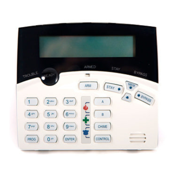
KEYPAD TAMPER OPTION SETTING Switch marked D used to Enable and Disable the Keypad Tamper option: TAMPER DISABLE TAMPER ENABLE LED KEYPAD FUNCTIONS The PW-4 LED Keypad consists of; an 18 button, backlit silicone rubber keypad, 14 LED ICON indicators and an internal piezo buzzer housed in a modern white plastic housing. -
Page 12: Accessing & Exiting Program Modes
PROGRAMMING YOUR PW-4 HOW TO PROGRAM The programming sequence always follows this pattern: <PROGRAM> - <1,2 or 3 digit address> - <ENTER> Client Mode 3 short beeps if OK - 1 long beep if error The LEDs will display current value or status Enter the new value or option <New Value>... -
Page 13: User Code Programming
TO EXIT PROGRAM MODES To exit either program mode when you have finished programming: Press <PROGRAM> - < ENTER> Program light goes out The panel is now back in Run Mode, any program changes you have made will have replaced previous values and be in effect. -
Page 14: User Code Options
USER CODE OPTIONS USER CODE PERMISSIONS (Code Options) - P21E-P30E Option 1 - Code has Area A permissions Option 2 - Code has Area B permissions Option 3 - Code can Arm Area User 1 Options Option 4 - Code can Disarm Area Option 5 - Code can turn STAY on 1 2 3 4 5 6 7 8 Option 6 - Code can turn STAY off... - Page 15 Option 4 Lockout Once Reset - This option is used to limit the output to one operation per arming period. Option 5 Siren Driver to Output - This option causes the output to be a modulated output designed to drive 8 ohm 10 watt horn speakers directly.
-
Page 16: Zone Alarms To Outputs
Option 3 Keypad Fire to Output - This option is used to map the manual Keypad Fire alarm function to an output. The keypad Fire alarm is generated when a user presses buttons 4 & 6 Simultaneously at the keypad. Option 4 Keypad Medical to Output - This option is used to map the manual Keypad Medical alarm... -
Page 17: Hour Alarms To Outputs
MAPPING 24 HOUR ZONE ALARMS TO OUTPUT 24 HOUR ZONE ALARM MAPPING TO OUTPUTS - P71E - P7 When a 24 Hour zone is in alarm this block of addresses allows individual zones to be mapped to selected outputs. The default setting is that zones 1 -4 will turn on output 2 only when a 24 Hour alarm occurs. -
Page 18: Radio Pendants To Outputs
MAPPING RADIO KEYS TO OUTPUTS RADIO KEY(PENDANT) MAPPING TO OUTPUTS - P101E - P108E When a Radio Key is to be used to operate a garage door or similar function this block of addresses allows individual Radio Keys to be mapped to selected outputs. The default setting is that none of the 8 Radio Keys are mapped to any outputs. -
Page 19: Area "A" Options
Option 5 “STAY” button can disarm Stay Mode - This option allows the “Stay” button to disarm STAY mode at any time (including when Stay Mode is fully set). If the option is off then Stay Mode can only be unset by a valid code. - Page 20 Option 7 Pulse on Arming to output - This option will map a pulse to the Output each time Area"A" is armed ( the length of the pulses is set by the pulse timer P221E-P228E). Option 8 Pulse on Disarming to output - This option will map a pulse to the Output each time Area"A" is disarmed ( the length of the pulses is set by the pulse timer P221E -P228E).
-
Page 21: Area "B" Options
will change the arm/disarm state). The panel tamper input is used to provide the key-switch function. AreaB Option - - - 4 5 - - - PARTITION “B” OUTPUT OPTIONS PARTITION “B” OUTPUT OPTIONS - P121E - P128E This block of addresses sets a number of output options which are specific and unique to the operation of partition or Area "B". -
Page 22: Zone Doubling
PROGRAMMING ZONE EOL OPTIONS ZONE EOL INPUT (4 zones) - P130E - Default=1-4 OFF P130E 1-8E Zone EOL input - This option is used to define the PW-4 as a 4 zone panel with or without EOL (End of Line Resistors) . Options 1-4 relate to zones 1-4 respectively and decide whether the zone input requires an end of line resistor or just a short or open circuit to seal the zone. - Page 23 entry delay time will apply provided a non-handover zone is triggered before the handover zone. If no other entry delays are active when the handover zone is triggered, the zone will activate immediately. P138E Two Trigger Zone Zones 1-4. (Default = No zones) This option allows programming of which zones will require two triggers before they activate.
-
Page 24: Zone Inactivity Timer
P148E Report Zone Tampers to Dialer Zones 1-4. (Default = All zones) This option allows the programming of zone tampers to be sent via the dialer to a Monitoring Station. P149E Zone Reports Area “B” Account Zones 1-4. (Default = All zones) When a zone is in both partitions A&B this address allows the option of specifying which account number a zone alarm will report to. -
Page 25: Day Mode Timer To Keypad Buzzer
DAY MODE TO KEYPAD BUZZER TIMER These addresses can be programmed to have a value from 0 to 99 but the value is in 1/10 of a second increments. This means the default of 20 at addresses P209E & P210E is equal to 2 seconds. -
Page 26: Loading Radio Zones
Option 1 Crow AE Series Battery Low - If a Crow (AE) radio pendant or PIR is used on the PW-4 radio zone input, setting this bit allows the panel to correctly recognize the battery low signal from Crow devices. -
Page 27: Loading Radio Pendants
Option 11 Ness Battery Low - If a Ness radio pendant or PIR is used on the PW-4 radio zone input, setting this bit allows the panel to correctly recognize the battery low signal from Ness devices. Option 12 Ness Radio Reed Switch - If a Ness radio reed switch is used on the PW-4 radio zone input, setting this bit allows the panel to correctly recognize the battery low signal from Ness device. -
Page 28: Radio Pendant Options "A
P616E Load Radio Pendant # 6 P617E Load Radio Pendant # 7 P618E Load Radio Pendant # 8 RADIO PENDANT OPTIONS “A” RADIO PENDANT OPTIONS “A”- P151E-P158E This block of addresses (P151E - P158E) are used to select the operational settings for each of the 8 radio pendants. -
Page 29: Keypad Partition Assignment
pendants. To prevent confusion, if a pendant is set to control an output or provide instant Panic, then you should turn off any Arm or Disarm options at addresses P151E-P158E. P161E-Pendant #1 Options Turn output ON - Default off Turn output OFF - Default off Visonic Powercode Battery Low - Default off Spare - Default off Report Pendant Panic To Dialer - Default off... -
Page 30: Keypad Panic Button Enable/Options
KEYPADS WITH PANIC BUTTON ENABLED The panic button on all keypads can be set for delayed or instant operation. If you do not want the Panic function enabled at any of the keypads you can disable the operation at this address. This option may be useful where a keypad has to be installed in a public area. - Page 31 FIRE ALARM TO KEYPAD BUZZER The two button fire function at the keypads (P176E) can be audible or silent at the keypads. If a silent fire alarm is required the option must be turned off at this address. For an audible Panic Beep at the keypad/s turn this option on.
-
Page 32: Miscellaneous Panel Options.#1
MISCELLANEOUS PANEL OPTIONS # 1 This address (P169E) is used to select the first set of optional panel functions. P169E Turn Off keypad LEDS at the end of exit time - Default off Keypad Panic Button delayed or instant - Default off Installer Code has direct access to Program Mode - Default on Option 1 Turn off keypad LEDS at end of exit time - If this option is off (LED 1 Off) then the keypad LEDS... -
Page 33: Duress Digit
Option 6 No audible keypad beep on zone inactivity timeout - If a zone is set for inactivity monitoring (P150E) and it does not unseal at least once during the timeout period (P240E) an alarm will be generated. An inactivity timeout will cause the trouble LED on the keypad to flash and the zone led that failed will be on solid. -
Page 34: Reset Defaults
P412E Daylight Saving End Month - Value 1-12 - Default = 3 P413E Daylight Saving End Hour - Value 0-23 - Default = 3 When setting up a panel for the first time using daylight saving, you must ascertain whether daylight saving is currently ACTIVE. -
Page 35: Data Transfer Unit(Dtu)
All Walk test activities will go into the event memory for display via the LCD keypad or LED keypad , In memory display mode P627E Walk-test Mode Walk Test Mode - - - - - - - - WRITE TO EEPROM (DTU) BOARD This address (P628E) is used to copy the panels program configuration to an external EPROM memory card (DTU- Data Transfer Unit) which can be plugged into the expansion socket on the control board. -
Page 36: Dialer Programming Options
DIALER PROGRAMMING SECTION The Dialer section of this alarm panel has many different programmable options. Some of these options require special function keys to select or program the options when entering telephone numbers or 4+2 codes. These special function keys and their corresponding keypad LED indications are listed in the following table LED KEYPAD LED KEYPAD LCD KEYPAD... - Page 37 panel to only communicate in one format. If the LED is off the format is Bell 103, LED on means V21. Dialer Options 1 2 - - - - 7 - DIALER REPORTING OPTIONS “A” This address (P186E) is used to enable or disable various alarm reports to the Dialer. P186E Report Duress Alarm - Default on Report Mains Fail - Default on...
-
Page 38: Phone Number Programming & Options
Spare Spare Spare Spare Option 1 Report Keypad Panic Alarms - If the single button “Panic” or the 2 button “1&3” Panic alarm features are enabled then turning this on option allows the Panic Alarm to be sent via the dialer to a monitoring station. - Page 39 PROGRAMMING TELEPHONE NUMBERS The panel can be programmed with up 4 telephone numbers. The numbers can be up 16 digits long. Dial modifiers such as Pause can be programmed into the number sequence as per the chart below. See the table on page 32 for more information on the special telephone number characters/modifiers.
- Page 40 P404E. Option 3 Pager - Report alarm events using CROW "Pager" format. This format utilizes Telecoms’ 026 pager network or other public subscriber networks, etc, to send numeric messages to a compatible pager.
-
Page 41: Contact Id Reporting Codes
PROGRAMMING TELEPHONE NUMBER REPORT OPTIONS This block of addresses (P181E - P184E) are used to set the reporting options for each telephone number P181E-Telephone #1 Options 1E Stop if Kissed Off - Default on Stay Call Progress - Default on Blind Dial - Default off Use Group Codes or Multiple Accounts - Default off Send Restores - Default on... -
Page 42: 4+2 Reporting Codes
ZONE CONTACT ID CODE This block of addresses (P321E - P324E) are used to set the Contact ID code that a Zone will transmit in an alarm. If a value of “0” or the “Bypass” button is entered at any of these addresses then the zone will not report via the Dialer. P321E Zone # 1 Contact ID Code - 3 Digit Number (Default = 130) P322E... - Page 43 programmed into any 4+2 address (or the “Bypass” key is entered at a selected 4+2 address) then no report will be generated for that event. ZONE ALARM 4 + 2 REPORTING CODE This block of addresses (P511E - P514E) are used to set the 4 + 2 code that a Zone will transmit in an alarm. P511E Zone # 1 4 + 2 Code - 2 Digit Number (Default = 01) P512E...
- Page 44 P519E System Tamper 4 + 2 Code - 2 Digit Number (Default = 86) P531E Panic Alarm 4 + 2 Code - 2 Digit Number (Default = 88) P532E Fire Alarm 4 + 2 Code - 2 Digit Number (Default = 89) 4+2 Low Battery P533E Medical Alarm 4 + 2 Code - 2 Digit Number (Default = 90)
-
Page 45: Voice Board & Dtmf Code Programming
ARMED BY RADIO USER 4 + 2 CODE This block of addresses are used to set the 4 + 2 code that will transmitted each time an individual User Arms the alarm system via there Radio Key. P561E Armed by Radio User # 1 4 + 2 Code - 2 Digit Number (Default = 61) P562E Armed by Radio User # 2 4 + 2 Code - 2 Digit Number (Default = 62) P563E... -
Page 46: Upload/Download Security Code
MISCELLANEOUS VOICE BOARD MESSAGES This block of addresses (P259E - P262E) are used to select a voice message that various Alarms will transmit via the dialer. For this option to work the optional Voice Board Must be fitted. If a value of “0” or the “Bypass” button is entered at any of these addresses then the alarm will not report via the Dialer in either Voice or Domestic modes. - Page 47 MAINS FAIL REPORTING DELAY This address (P319E) is used to set a timer that delays the reporting of Mains Failure to a Monitoring Station. If the mains voltage returns before the timer expires then no report is sent. P319E Mains Failure Report Delay - Value 0-9999 Seconds (Default = 600) Mains Fail Report SETTING DIALER TEST REPORT PARAMETERS This option sets the days of the week and the time when an automatic test report is sent to a central monitoring...
-
Page 48: Program Summary
PW-4 PROGRAM SUMMARY GUIDE The following program summary is an abbreviated version of all the PW-4 program addresses. This is intended as a quick guide to finding a program address. The program addresses are in numerical order with page references beside them so you can get more detailed information if required. - Page 49 P47E Options for Output # 7 (Default None) 6 = Duress Alarm to Output P48E Options for Output # 8 (Default None) 7 = Mains Fail to Output 8 = Battery Low to output Mapping Zone Alarms To Outputs P51E Normal Zone Alarms 1-4 to Output # 1 (Default= All Zones) Page 16 P52E...
- Page 50 P94E Zone Tamper 1-8 to Output # 4 (Default= None) Page 17 P95E Zone Tamper 1-8 to Output # 5 (Default= None) Page 17 P96E Zone Tamper 1-8 to Output # 6 (Default= None) Page 17 P97E Zone Tamper 1-8 to Output # 7 (Default= None) Page 17 P98E Zone Tamper 1-8 to Output # 8 (Default= None)
- Page 51 Partition “B” Output Options P121E Area “B” Opt. O/P # 1 (Default= None) P111E-P114E Options Page 21 P122E Area “B” Opt. O/P # 2 (Default= None) 1 = Arm Status to Output P123E Area “B” Opt. O/P # 3 (Default= None) 2 = Stay Arm Status to Output P124E Area “B”...
- Page 52 P165E Radio Key # 5 Options (Default= None) 4 = Spare Page 29 P166E Radio Key # 6 Options (Default= None) 5 = Send Panic Alarm Through Dialer Page 29 P167E Radio Key # 7 Options (Default= None) 6 = Causes Immediate Panic Page 29 P168E Radio Key # 8 Options (Default= None) 7 = Causes Delayed Panic ( 1.5 Sec) Page 29...
- Page 53 Keypads Medical (7&9) or (A&B) Enabled P178E Keypads Medical 7 & 9 or A&B Function Enabled - Value Keypad 1-8 (Default= No Keypads) Page 31 Medical Beep to Keypad Enabled P179E Medical Beep to Keypad Enabled - Value Keypad 1-8 (Default= No Keypads) Page 31 Stay Button can Disarm when in Stay Mode Enabled P180E Stay Button can Disarm when in Stay Mode - Value Keypad 1-8 (Default 1 &...
- Page 54 **Dialer Reporting Options “C”** P188E Dialer Options for “B” P188E Options (Default = 1,2) Page 38 1 = Report Arm/Disarm 2 = Report Stay Mode Arm/Disarm 3 = Report Disarm only after an Activation 4 = Report Stay Mode Disarm only after an Activ ation 5 = Report 24 Hour Alarms when set to Domestic/Voice mode 6 = Send arm immediate or after exit delay 7 = Report Zone alarms in Stay Mode...
- Page 55 P233E Options for Zone # 3 (Default= 0) 2 = Crow AE Radio Reed Switch Page 26 P234E Options for Zone # 4 (Default= 0) 3 = Crow Merlin PIR (supervised signal ignored) Page 26 4 = Crow Merlin PIR (supervised signal active) Page 26...
- Page 56 **Auto-Answer Ring Count** P249E Auto-Answer Ring Count - Value 0-99 (Default = 25) Page 46 **Start of DTMF Remote Control Messages** P250E Start of DTMF Remote Control Messages - Value 0-99 (Default = 0) Page 46 **Programming Voice Board Messages** P251E Zone 1 Voice Message Number - (Default = 1) Page 45 P252E Zone 2 Voice Message Number - (Default = 1)
- Page 57 **Keypad Panic Alarm Contact ID Reporting Code** P329E Keypad Panic (“Panic” or “1&3”) Contact ID Code (Default=120) Page 42 **Keypad Fire Alarm Contact ID Reporting Code** P330E Keypad Fire (4&6) Contact ID Code (Default=110) Page 42 **Keypad Medical Alarm Contact ID Reporting Code** P331E Keypad Medical (7&9) Contact ID Code (Default=100) Page 42 **DTMF Remote Control Codes**...
- Page 58 **Contact ID Account Codes** P506E Contact ID Partition “A” Account Code Number - 4 Digits (Default = 0000) Page 41 P507E Contact ID Partition “B” Account Code Number - 4 Digits (Default = 0000) Page 41 **Zone Alarm 4+2 Reporting Code** P511E 4+2 Alarm Code for Zone 1 (Default=01) Page 43 P512E 4+2 Alarm Code for Zone 2 (Default=02)
- Page 59 **Mains & Battery 4+2 Restore Codes** P539E Low Battery Restore 4+2 Code (Default=96) Page 44 P540E Mains Failure restore 4+2 Code (Default=97) Page 44 **Armed by User # 4+2 Reporting Code** P541E 4+2 Arm Code for User 1 (Default=41) Page 44 P542E 4+2 Arm Code for User 2 (Default=42) Page 44 P543E 4+2 Arm Code for User 3 (Default=43)
- Page 60 **Disarmed by Radio Pendant User # 4+2 Reporting Code** P571E 4+2 Disarm Code for Radio User 1 (Default=71) Page 45 P572E 4+2 Disarm Code for Radio User 2 (Default=72) Page 45 P573E 4+2 Disarm Code for Radio User 3 (Default=73) Page 45 P574E 4+2 Disarm Code for Radio User 4 (Default=74) Page 45...
- Page 61 Restore All Factory Defaults P620E Restore All Factory Defaults Page 34 Restore User Code Defaults P621E Restore User Code Defaults Page 34 Restore Addresses 20-199 to Factory Defaults P622E Restore Addresses 20-199 to Factory Defaults Page 34 Restore Addresses 200-399 to Factory Defaults P623E Restore Addresses 200-399 to Factory Defaults Page 34 Restore Addresses 500-599 to Factory Defaults...
- Page 62 Contact ID Code Summary In addition to the programmable Contact ID code assignments defined at P 321E - P331E there are a number of event codes with extensions pre-defined as listed below. This extensions list is for your reference only and can not be re-assigned.
- Page 63 March 2002 PowerWave V8.62 and above. To the best of our knowledge the information contained in this manual is correct at the time of printing. Crow Electronic Engineering Ltd. reserve the right to make changes to the features and specifications at any time without notice in the course.
- Page 64 Page 64...
Need help?
Do you have a question about the PowerWave-4 and is the answer not in the manual?
Questions and answers