
Related Manuals for SANTA CRUZ MY18 Nomad


Summary of Contents for SANTA CRUZ MY18 Nomad
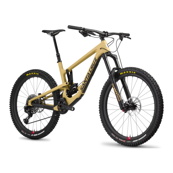
- Page 1 SANTA CRUZ BICYCLES Cable Routing Procedure MY18 Nomad Copyright Santa Cruz Bicycles 2017...
-
Page 2: Table Of Contents
TABLE OF CONTENTS SAFETY INSTRUCTIONS ................3 CABLE ROUTING..................... 3 INTRODUCTION ..........................3 TOOLS AND SUPPLIES ......................3 REAR DERAILLEUR ROUTING ..............4 REAR BRAKE ROUTING ................. 8 FRONT BRAKE ROUTING ................11 DROPPER POST ROUTING - HYDRAULIC-ACTUATED REMOTE ..12 DROPPER POST ROUTING - CABLE-ACTUATED REMOTE ....14 MAINTENANCE SCHEDULE ................. -
Page 3: Safety Instructions
For current service instructions, part numbers, and technical information, visit www.santacruzbicycles.com, Please contact your local Santa Cruz Bicycles® distributor or dealer for questions and orders. Information contained in this publication is subject to change at any time without prior notice. The appearance of your product appearance may differ from the images contained in this publication. -
Page 4: Rear Derailleur Routing
REAR DERAILLEUR ROUTING 1. Install your rear derailleur and shifter according to your manufacturer’s instructions (not pictured). 2. Determine the correct length of cable housing. Push one end of the housing into the access port at the back end of the seat stay until it exits the access port at the front end of the seat stay. - Page 5 4. Route the housing into the downtube access port until it exits the non-drive side access port at the head tube. There should be a gentle bend in the housing from the seat stay to the downtube. 5. Make sure the housing is long enough to allow the handlebar to rotate 180 degrees to each side without pulling the housing from the rear derailleur cable stop or...
- Page 6 7. Install a ferrule onto the both ends of the housing. 8. Slide the cable into the housing until it exits at the rear derailleur. Make sure the housing and ferrule are seated in the shift lever.
- Page 7 9. Seat the ferrule and housing into the cable stop of the rear derailleur. 10. Install the cable into the rear derailleur according to your manufacturer’s instructions (not pictured). 11. Apply a small amount of silicon bike spray to the outside of the two rubber grommets and install them into the access ports.
-
Page 8: Rear Brake Routing
REAR BRAKE ROUTING 1. The rear brake line is already connected to the lever and caliper. Install the caliper according to your brake manufacturer’s instructions. 2. Use a 6 mm hex wrench to loosen and remove the shock mounting bolt of the upper link. - Page 9 3. Pull up on the rear triangle to move the frame into its travel until there’s room to fit the lever through the seat tube and the non-drive side rear triangle. Make sure to route the line on the inside of the seat stay.
- Page 10 6. Use zip ties to attach the brake line to the anchors of the non-drive side down tube and seat stay. Create a gentle bend from the anchor of the downtube to the anchor of the seat stay. 7. Make sure the line is long enough to allow the handlebar to rotate 180 degrees to each side.
-
Page 11: Front Brake Routing
FRONT BRAKE ROUTING 1. The front brake line is already connected to the lever and caliper. Consult your brake manufacturer’s instruction for installation information. 2. Install the lever and caliper according to your brake manufacturer’s instructions (not pictured). 3. Attach the brake line to the fork according to your brake manufacturer’s instructions (not pictured). -
Page 12: Dropper Post Routing - Hydraulic-Actuated Remote
DROPPER POST ROUTING - HYDRAULIC-ACTUATED REMOTE 1. Disconnect the hydraulic line from the remote to the seatpost according to your dropper post manufacturer’s instructions (not pictured). 2. Install the remote onto the handlebar according to your manufacturer’s instructions (not pictured). 3. - Page 13 5. Set the approximate seat height. 6. Make sure the housing is long enough to allow the handlebar to rotate 180 degrees to each side. 7. Apply a small amount of silicone bike spray to the outside of the rubber grommet to install it into the access port.
-
Page 14: Dropper Post Routing - Cable-Actuated Remote
DROPPER POST ROUTING - CABLE-ACTUATED REMOTE 1. Determine the correct length of cable housing. Push one end of the housing into the drive side access port until it exits the top of the seat tube. 2. Install the remote and seatpost according to your seatpost manufacturer’s instructions (not pictured). - Page 15 4. Make sure the line is long enough to allow the handlebar to rotate 180 degrees to each side. 5. Use a cable cutter to cut the housing to the correct length (not pictured). Tip: use pliers to round out the housing after the cut, as oval-shaped housing can apply unwanted friction on the cable.
- Page 16 7. Slide the cable into the housing until it exits at the seatpost. 8. Make sure the housing and ferrule (if applicable) are seated in the remote. 9. Install the cable and housing according to your seatpost manufacturer’s instructions (not pictured).
- Page 17 10. Apply a small amount of silicon bike spray to the outside of the rubber grommet to install it into the access port.
-
Page 18: Maintenance Schedule
MAINTENANCE SCHEDULE Bicycle service requires special knowledge and tools and should be performed by a professional bicycle mechanic. This user manual is to be used in conjunction with the manuals supplied by the component manufacturers. If you did not receive the manual provided by the component manufacturer, download the materials off the Internet or contact your local dealer. -
Page 19: Warranty
LIFETIME FRAME AND FORK WARRANTY Santa Cruz Bicycles will repair or replace at its option any frame or rigid fork made by Santa Cruz Bicycles it determines to be defective in materials or workmanship. The warranty will be in effect for the lifetime of the frame or rigid fork and is available only to the original, registered owner. - Page 20 NOTES...
- Page 21 This page is intentionally left blank.
- Page 22 Santa Cruz Bicycles 2841 Mission Street Santa Cruz, CA. 95060 santacruzbicycles.com Copyright Santa Cruz Bicycles 2017...
Need help?
Do you have a question about the MY18 Nomad and is the answer not in the manual?
Questions and answers