Table of Contents
Advertisement
Quick Links
Advertisement
Table of Contents

Related Manuals for RuggON MT7000

Summary of Contents for RuggON MT7000
- Page 1 MT7000 User’s Manual v1.3...
-
Page 2: Table Of Contents
....................................11 I/O P ORTS ................................ 12 IMENSION AND EIGHT MT7000 Standard ................................12 MT7000 with I/O water-proof box ..........................13 .................................... 14 ACKAGE CHAPTER 2. HARDWARE INSTALLATION ...................... 15 ..................................15 SATA M ODULE Installing/Removing a mSATA Module ........................15 ........................ - Page 3 ................................ 26 OWERING THE YSTEM Connector Power ................................26 Powering Down the System ............................28 ....................................29 LED S TATUS ............................30 DJUST THE PEAKER OLUME ............................30 RIGHTNESS DJUSTMENT ................................. 31 NTERNAL ICROPHONE ..............................31 ROGRAMMABLE UTTONS ................................31 OWER ANAGEMENT CHAPTER 5.
- Page 4 CHAPTER 7. MAIN BIOS SETTING ........................60 ................................60 EQUENCE ............................. 61 ET THE SYSTEM CONFIGURATION Setting the System Date ..............................61 Setting the System Time ..............................61 ................................62 YSTEM NFORMATION ..................................62 EATURES ............................. 63 ISCELLANEOUS ONFIGURATION ............................63 ’...
-
Page 5: Safety Precautions
Safety Precautions Read these safety instructions carefully. Keep this user’s manual for later reference. Disconnect this equipment from any AC outlet before cleaning. Use a damp cloth. Do not use liquid or spray detergents for cleaning. For plug-in equipment, the power outlet socket must be located near the equipment and must be easily accessible. - Page 6 user’s manual. e. The equipment has been dropped and damaged. f. The equipment has obvious signs of breakage. 16. Do not place heavy objects on the equipment. 17. The unit uses a three-wire ground cable which is equipped with a third pin to ground the unit and prevent electric shock.
-
Page 7: Regulatory And Certification
Regulatory and Certification This device complies with Part 15 of the FCC Rules. Operation is subject to the following two conditions: 1. This device may not cause harmful interference. 2. This device must accept any interference received, including interference that may cause undesired operation. -
Page 8: Ce Marking
CE Marking This product has passed the CE test for environmental specifications when shielded cables are used for external wiring. We recommend the use of shielded cables. Please contact your local representative for ordering information. This product has passed the CE test for environmental specifications. Test conditions for passing included the equipment being operated within an industrial enclosure. -
Page 9: Chapter 1. Product Introduction
Chapter 1. Product Introduction MT7000 is an in-vehicle terminal with 7” high resolution display and 500nits brightness, and is flexible to support a wide range of wireless connection capability. The device is well-suited for fleet management, asset management, EOBR and ELDs application. -
Page 10: Environment
Environment Operating temperature: -30°C (-22°F) to 60°C (140°F) In accordance with MIL-STD-810G CHANGE1 Method 501.6 High Temperature Procedure II - Operation In accordance with MIL-STD-810G CHANGE1 Method 502.6 Low Temperature Procedure II – Operation Storage temperature: ... -
Page 11: I/O Ports
I/O Ports Item Description RS-232 x 1 with 0/5/12V support 0.6A (COM1) Serial RS-232 TX, RX/422/485 x 1 (COM2) USB 3.0 x 1 USB 2.0 x 1 Ethernet Gigabit RJ45 x 1 2 DI + 2 DO Digital I/O SOS x 1 CAN bus (SAE J1939 supported) x 1 Headset jack x 1 Audio... -
Page 12: Dimension And Weight
Dimension and Weight MT7000 Standard Dimension: 219.98 x 151.98 x 40.8mm / 8.66 x 5.98 x 1.60in. (W x H x D) Weight: 1.25 kg/ 2.76 lbs. (with mSATA) Front View Dimension Side View Dimension... -
Page 13: Mt7000 With I/O Water-Proof Box
MT7000 with I/O water-proof box Dimension: 219.98 x 182.87 x 42.4mm / 8.66 x 7.20 x 1.67in. (W x H x D) Weight: 1.27 kg/ 2.8 lbs. (with mSATA) Front View Dimension Side View Dimension... -
Page 14: Package List
Contact your representative if there are any missing or damaged items. Please verify the delivery of the contents upon receipt MT7000 in-vehicle terminal Bare wire power cable with circular power code 2-feet DB15 male connector cable with multiple end ... -
Page 15: Chapter 2. Hardware Installation
Chapter 2. Hardware Installation This chapter provides information for the installation and removal of mSATA and mini PCIe card. mSATA Module Prevention of EMI interference in this device is not guaranteed if the original components are replaced. A single mSATA module slot is available for memory expansion. The device supports up to 256GB. - Page 16 Remove the service door. Remove the shielding can. Locate the mSATA module slot; see the following image. Insert the mSATA module into the slot and then fasten the screws or loosen the screws to remove the module. Replace the service cover.
-
Page 17: Installing/Removing The Wi-Fi Module
Installing/Removing the Wi-Fi Module MT7000 supports Mini PCIe slot in full size for Wi-Fi radio card installation; it includes PCIe and USB signal for Wi-Fi and Bluetooth combo card. The Wi-Fi module is pre-installed when you order the MT7000. To install or remove the Wi-Fi module, please follow the guidelines below. -
Page 18: Installing/Removing The Sim Card
Half-size Mini PCIe Card 4. Fasten/Loosen the corresponding screws to install/remove the card. Note: If you are installing the Wi-Fi module, after fastening the screws, connect the internal antenna cables to the card. If you are removing the Wi-Fi module, before loosening the screws, disconnect the internal antenna cable from the card. -
Page 19: Internal Sim Slot
the following guidelines to install or remove the SIM card. Please make sure that the device is completely powered off and make sure the power status LED light is off when installing/removing the internal SIM card. Internal SIM slot 1. Shut down the system properly and disconnect the device from all power sources. 2. -
Page 20: External Sim Slot
7. Insert the SIM card into the SIM card holder. 8. Close the cover of the SIM card holder. External SIM slot 1. Shut down the system properly and disconnect the device from all power sources. 2. Open the side cover; you can see the Mini SIM card and SD card slot. SIM Card Slot SD Card Slot 3. -
Page 21: Installing/Removing The Wwan Module
2. Un-mount the device from the mounting apparatus; make sure that the display surface is protected. 3. Open the service cover; locate the WWAN module slot on the MT7000. Please make sure that the device is completely powered off and make sure the power status LED light is off when removing WWAN module. - Page 22 1. Please turn over the mini WWAN module and lock it according to the position of the extension bracket (Note: Please make sure to lock the WWAN module on the back side). 2. Please turn over the mini WWAN module on the front side (along with the extension bracket) and lock it onto MT7000 accordingly.
-
Page 23: Installing Wwan/Wlan Antennas
After you installed the WWAN module, you need to connect the antenna for use. Please note MT7000 supports internal (optional) or external WWAN antenna. If you would like to use the internal or external WWAN antenna, you need to manually disable either one of them. The following section will guide you through how to change and use your internal/ external antenna. -
Page 24: External Antenna
Internal antenna (optional) under the cover External antenna External Antenna 1. Locate the external antenna cable. 2. Use external antenna cable to connect the black cable to the connector labeled MAIN and the grey cable to the connector labeled AUX. MAIN... -
Page 25: Chapter 3. Hardware Mounting
Chapter 3. Hardware Mounting The MT7000 supports a standard VESA version MIS-D, 75, C (75mm distance quadrate order, M5 thread, deepness 6mm) through the four drill holes on the back side of the device. Notes: To prevent any damage or injury, make sure the mounting bracket is... -
Page 26: Chapter 4. Start Up
Powering the System Connector Power MT7000 allows a wide range of DC power input from 9~36V via a 3-pin circular power cord. There are two options to start up the MT7000 via car power cable or external power adapter. Here is the 3-pin circular power cord. - Page 27 Top of the arrow mark 3. Twist the nut to lock the power connector to the device. 4. MT7000 will turn on automatically when the power supply is connected to the device. Power source from external power adapter If your power source is from external power adapter, it means the power source isn’t controlled by AAC/Ignition signal.
-
Page 28: Powering Down The System
Powering Down the System MT7000 will be auto power off in one minute when the power supply is removed. If you use software to power off the system, please remember to remove the power supply too; otherwise, the device will auto reboot again. -
Page 29: Led Status
LED Status The LEDs on MT7000 are status indicators that show the operating status of your system. The status indicators can help pinpoint possible failed hardware components causing specific symptoms. There are two status indicators in the front panel. Refer to the description below. -
Page 30: Adjust The Speaker Volume
When you use MT7000, you may well encounter different lighting conditions that make it difficult to see the information on screen. MT7000’s built-in ambient light sensor on the front panel supports auto-dimming, which you can also disable to manually adjust the screen’s... -
Page 31: Internal Microphone
Internal Microphone MT7000 is equipped with an internal microphone, so you don’t need an external one. In addition to the built-in speaker and microphones, you can plug external headsets in the audio jack. Programmable Buttons MT7000 provides default commands for five programmable buttons. You can configure the programmable buttons via DashON to different commands or keyboard shortcuts to better fit your work style. -
Page 32: Chapter 5. Jumpers And Connectors
Chapter 5. Jumpers and Connectors Bottom View Power Input Connector GPS Antenna Connector (SMA Jack) GPIO, CANBus WWAN Antenna Connector (SMA Jack) USB, RS-232/422/485 (COM2) USB 2.0 RS-232 with PWR (COM1) -
Page 33: External Connectors Pin Assignments
External Connectors Pin Assignments Use this section as a reference for the pin assignments of the various ports available on the MT7000. Power Connector Signal ACC/ Ignition Note: Please refer to section 1 in Chapter 4 for connecting the external power cable to power... -
Page 34: Rs-232 Port (Com1)
RS-232 Port (COM1) Signal Description Data carrier detect (input) Receive data (input) Transmit data (output) Data terminal ready (output) Signal/power ground Data set ready (input) Request to send (output) Clear to send (input) RI / PWR Bar code scanner power (1 A max) or Ring indicator (input) -
Page 35: Usb And Rs-232/422/485 Port (Com2)
USB and RS-232/422/485 Port (COM2) Signal RS-422 TX+ RS-422 RX+ RS-485 TX+ RS-232 TX RS-422 TX- RS-422 RX- RS-485 TX- USB 5V RS-232 RX USB DP USB DM USB 5V We provide Y-cable with DB15 male connector which is the RS232/422/485 and USB converter. - Page 36 RS-232/422/485 and USB Cable This Y-cable with DB15 male connector is the RS232/422/485 and USB converter. The other end of this Y-cable contains one USB type A jack for USB2.0 and one DB9 male connector for RS232/422/485. If you like to use RS232 or RS422 or RS485, please refer to the pin definition below.
-
Page 37: Digital I/O And Canbus Port
Digital I/O and CANbus Port Signal CAN_H WHEELTICK CAN_L CARD POWER DIO_OUT1 (5V 10mA) DIO_IN1 (5V 100mA) DIO_IN2 (5V 100mA) DIO_OUT2 (5V 10mA) We provide the DB15 male connector to multiple pins without termination cable. Please contact your local representative for ordering information... -
Page 38: Chapter 6. Dashon Setting
Chapter 6. DashON Setting You can use DashON to configure the device for your demo or test. We also provide the corresponding SDK for your application development. DashON will auto-run in background while the system turns on. This section is to brief you on what functions are included in DashON and how to set up based on Windows OS. -
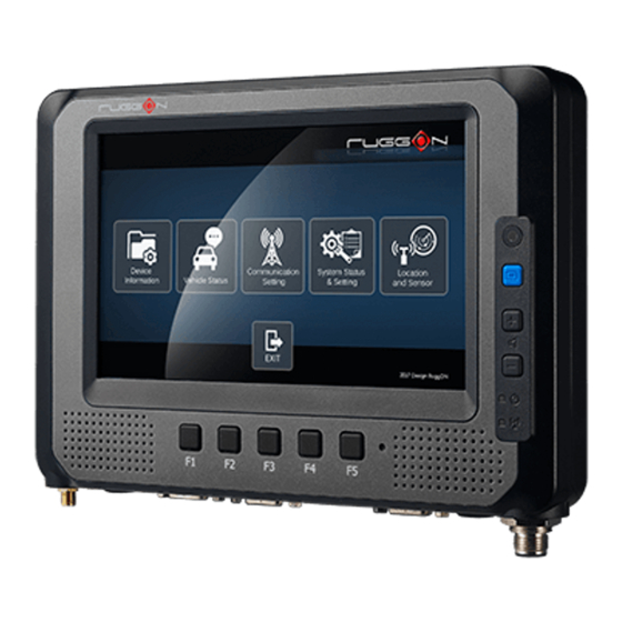
Page 39: Device Information
Device Information Click on the “Device Information” icon In device information, you can see the PCBA version, DashON utility version, BIOS version, EC version and system model name. -
Page 40: Vehicle Status
Vehicle Status Vehicle status shows some vehicle information from the simulator. The related AT command is available upon request. Please contact local sales representatives or login to the support website. -
Page 41: Communication Setting
Communication Setting Communication setting allows you to enable/disable Wi-Fi/WWAN/Bluetooth via DashON utility. Please click on the “Communication Setting” Enable/ Disable Module Item 1. Click on the switch bar to power on/ off the WWAN module. Item 2. Click on the switch bar to Enable/ Disable Wi-Fi function& Bluetooth function... -
Page 42: Wwan Communication Setting
WWAN Communication Setting If WWAN module is present in the device, you can click on “WWAN setting” to get into the detailed setting. You can set the two major features including WWAN RF on/off and SIM slot selection. 1. Module RF Enable/ Disable: to enable or disable the WWAN RF transmission. 2. -
Page 43: System Status & Setting
System Status & Setting This section is to set and read the system status. It covers power management, internal backup battery, I/O configuration, wake up event and so on. Power Automatic Turn Off Behavior When the system voltage drops below the UVP or when the power cable is disconnected, UVP is triggered and shuts down the system. - Page 44 Please click on the “Power Management” ACC Detection Setting In MT7000 design setting, it supports ACC sense. You can check its status from ACC status. Input Voltage Setting Click on the to select the input voltage setting. You can select the power input voltage either 9~36V or 12V or 24V. If 9~36V is selected, it means the system can be powered on while the voltage ranges from 9~36V.
- Page 45 If 12V or 24V is selected, you can also select the startup and shut down voltage setting.
- Page 46 If the above selection items do not meet your demands, please contact local sales representatives. Power On/Off Delay Setting Power on delay function enables you to power on the device after the ACC is on for a...
- Page 47 specified period of time. Enabled power off delay function lets the device remains on until the ACC is off for a specified period of time. Power On Delay You can set the system startup time after ACC is on. Switch the , click on the , and you will see the selection list.
-
Page 48: Wake Up Setting
Wake up Setting In additional to ACC sense, two wake-up events are enabled to power up the device. They belong to RTC wake up. Here is the setting method. “System Status & Setting”-> “System Status & Setting” ->”Wake up Setting” In Wake up setting, you can find “Wake on RTC”... - Page 49 RTC wake up setting Click on the , you can find RTC timer setting to set your desired time to power up the system. After you have finished with the setup, click on the “OK” to save the value. For example, if you set 06:00:00, it means the system will be powered up at 6 o’clock in the morning.
-
Page 50: I/O Configuration
Y-cable converter to the system. Please refer to the pin out description for correct connection. Brightness Setting Brightness adjustment is to optimize the operation of the backlight LEDs under a variety of daylight conditions. MT7000 supports auto-dimming and manually adjusts the brightness. If... -
Page 51: Watchdog Timer
You can also manually change the display brightness via programmable buttons or the bar adjustment in DashON. For programmable button setting, please see “Programmable Button “section. MT7000’s display brightness is set to automatic adjustment. You can also turn off “Auto-Dimming” and drag the scroll bar to adjust display brightness. - Page 52 icon “System Status & Setting”. Double click on the DashON icon, and then click on the 4 Click on the “Watchdog Timer”...
- Page 53 Select the timer setting. Turn on the watchdog switch. If you’d like to test if the watchdog timer is enabled and working, please click on the “simulation” icon. The “simulation” is to simulate the system on hang and reboot it after the set time frame.
-
Page 54: Programmable Button
Programmable Button Programmable buttons can be set to different functions per user’s definition. - Page 55 Select which function key button you want to set and then click on the to select the function from the list. User can also define the keystrokes for function keys by selecting the “User Defined Command” from the list.
-
Page 56: Location And Sensor
Location and Sensor MT7000 provides the GPS receiver and G-Sensor built-in. DashON provides both setting and information and also links to the Google map locations for demo applications. You can also use the general freeware GPS viewer to set GPS setting. - Page 57 After click on , you will see the following setting screen. The following is the function description. Module RF: to enable or disable the GPS receiving function. Serial Port Setting: to set COM port for GPS module connected on. Baud Rete Setting: to set the baud rate speed. Satellites: a GPS receiver uses satellites to pinpoint locations;...
-
Page 58: Enable/ Disable Gps Receiver
The default GPS receiver is enabled in MT7000. If you want to disable the receiver, switch “Module RF” to Serial Port Setting By selecting a COM port, you use the port from the list to connect to your GPS. MT7000 uses COM3 as its default setting for GPS receiver. -
Page 59: Baud Rate Setting
Baud Rate Setting It must be set to the same baud rate you are using in the GPS receiver. Use as high a Baud rate as possible. Baud Rates from 4800 to 115200 can be selected in DashON. The default is 9600. -
Page 60: Chapter 7. Main Bios Setting
Chapter 7. Main BIOS Setting MT7000 is equipped with a Phoenix BIOS, which is stored in EEPROM chip. This chapter provides information for BIOS main feature setting in hardware system. When the system turns on, press <F2> to enter Setup. -
Page 61: Set The System Configuration
Set the system configuration for basic system configuration; users can set the system’s date, time, menu Use the Main drive parameters, and related settings via the HDD Sub-menu. Setting the System Date Setting the System Time... -
Page 62: System Information
System Information It displays the system configuration information such as CPU, Memory size, and firmware version. Boot Features Users can set the boot options for CSM support or Quick Boot. Note if the operating system is Windows 8, please set the Boot Features [Off] for “Legacy Boot”... -
Page 63: Miscellaneous Configuration
Miscellaneous Configuration Use Advanced menu to set the system I/0 device function. Account’s Password Setting Use the Security Menu to establish the system password and protection for entering the BIOS or system start-up. -
Page 64: Hdd Security Setting
HDD Security Setting To establish password protection to restrict access to the contents of the hard disk drive, the HDD password is written to the system BIOS and to the hard disk drive to ensure that the password can protect your hard disk drive should it be moved to another computer. -
Page 65: Chapter 7. Wi-Fi Hotspot Setup
Chapter 7. Wi-Fi Hotspot Setup MT7000 can be a gateway role for other devices to connect to the Internet. Windows has ways to create Wi-Fi hotspot, and the feature is integrated into “Network and Sharing Center”. Here is how to turn your Windows 7 into a Wi-Fi hotspot. (The process should be similar for Windows 8) WWAN or LAN connection is properly connected to the Internet. - Page 66 Click on “Next” Enter the Network Name, choose a security type, and enter the security key. Check the “Save this network” checkbox; it will save your network name on the Wireless network connection, and then click on “Next”. MT7000...
- Page 67 At this point, your ad hoc network should be running and ready to start connecting your device. Click on the “Next”. MT7000 *********...
Need help?
Do you have a question about the MT7000 and is the answer not in the manual?
Questions and answers