Table of Contents

Subscribe to Our Youtube Channel
Related Manuals for isel automation GFV 44/33

Summary of Contents for isel automation GFV 44/33
- Page 1 isel flat bed installation 44/33 44/73 68/52 102/62 142/102 142/162 142/232 GFV 142/102 Operating and Maintenance Instruction B.2745xx/2002.04/E Order-number: _________________ Serial-number:__________________...
- Page 2 isel flat bed installation GFV On this Manual Various symbols are used in this Manual to quickly provide you with brief information. Danger Caution Note Example Additional Information © iselautomation GmbH & Co. KG All rights reserved. Despite all care, printing errors and mistakes cannot be ruled out completely. Suggestions for improvement and notes on errors are always welcomed.
-
Page 3: Table Of Contents
isel-flat bed installation GFV Contents Introduction ........................4 Intended use ........................5 Safety notes ........................6 Scope of delivery .......................7 Setting up and connection ....................8 Spacial requirements .......................8 Transportation .........................9 Setting-up ..........................9 Enclosure ..........................10 Wiring ........................... -
Page 4: Introduction
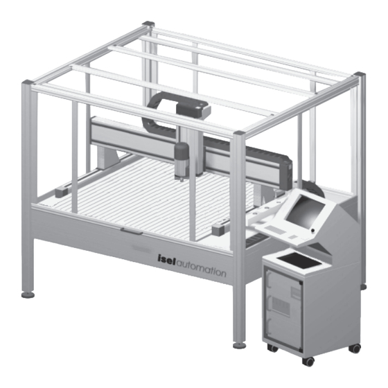
isel flat bed installation GFV Introduction The isel GFV Flat Bed Machining Systems are proven CNC machines that offer an abundance of possibilities for three-dimensional processing of work pieces. The machines are built and equipped in various sizes and designs. Tailored standard sections and drive elements that are combined according to requirements form the basis. -
Page 5: Intended Use
isel-flat bed installation GFV Intended use The flat bed equipment is a machine tool with several linear axes and a rotary axis. Motors and switches of the driving axes can be driven via computer. By default*, the complete control and power electronics of all axes are located in the external 19" Penguin II data terminal. -
Page 6: Safety Notes
isel flat bed installation GFV Safety notes • The machine may not be operated in an explosive atmosphere. • The machine is encased all around. The enclosure protects you against moving tools, decreases the operating noise level, and restrains the chips. During processing, the hood is bolted and can not be opened. -
Page 7: Scope Of Delivery
isel-flat bed installation GFV Scope of delivery The standard scope of delivery of the flat bed installations includs: • Aluminum basic rack including - enclosure - suction tube and connection adapter • Driving axes including limit switches • Operating console •... -
Page 8: Setting Up And Connection
Normally, the cover of the enclosure turns upwards. Thus, you must keep approx. 50 to 60 cm of free space in addition. > 500 mm Dimensions and spacial requirements Model GFV 44/33 1010 1750 2300 GFV 44/73... -
Page 9: Transportation
isel-flat bed installation GFV Transportation Remove the transport safeguards at the rack feet. Use only suitable lifting devices (fork-lift truck, lifting truck, see figure). Only raise the machine from below. Do not pull it up at the cover. During a later transportation, please ensure that the voltage supply and connection cables are not damaged. -
Page 10: Enclosure
isel flat bed installation GFV Place the machine onto a plane and solid surface. You can balance small unevennesses of the floor using the feet. To level the machine accuratetly, you need a spirit level with a minimal precision of 0,5 mm/m. 1. -
Page 11: Commissioning
isel-flat bed installation GFV Commissioning Preliminary notes This figure present an overview of the electronic components in the Penguin. Œ Œ Œ Œ Œ Emergency-Stop (at the operating console) Monitor Ž Ž Ž Ž Ž Keyboard ... -
Page 12: Cover Interlocking
isel flat bed installation GFV Memory For the computer to work error-free, approx. 600 Kbytes of conventional main memory and approx. 140 kilobytes of high memory should be available. You can check your memory when calling the Memmaker DOS program. There, enter: EMS —>... -
Page 13: Operating Console
isel-flat bed installation GFV Operating console The operation of the GFV is performed using a movable operating console. It helps to install the machine in an user-friendly manner. ΠΠΠΠΠEmergency-Stop ... removes power from the drive controller. Unlatching by turning to the right. -
Page 14: Activating The Software
isel flat bed installation GFV Activating the software The iseldrv.exe machine driver is already installed (DOS) on the control computer (CNC servo controller). You only have to load it before any start of the machining software. It is recommended to load the driver using the drv.bat batch file. (You activate the program and inform the computer where the default settings are stored for your machine.) If the file does not exist yet you can easily generate it yourself (edit drv.bat). -
Page 15: Operating Modes
isel-flat bed installation GFV Operating modes - Auto In the AUTO operating mode, a loaded program is automatically executed and thus your workpieces are machined. During processing, the cover is locked. You can only open the cover after the machine has reached the HOME position and the machine (spindle) is switched off. -
Page 16: Accessories
isel flat bed installation GFV Accessories You can order the following matching accessories for the GFV: • Clamping set (bolt lever, 2 dead stop rails, hollow wrenches) • Supplementary mounting material for the T-slot plate • Supplementary collets for the spindle: 1 to 5 mm in 0,5 mm steps, 6 mm and 1/8"... - Page 17 isel-flat bed installation GFV Exhaust system For an exhaust system, a suction tube with a connecting piece for the standard diameters 32, 35 and 38 mm is pre-installed. Connect a vacuum cleaner here. The other end of the suction tube ends at the Z- axis.
-
Page 18: Cleaning/Maintenance
isel flat bed installation GFV Cleaning/maintenance Turn off the mains switch before every cleaning and maintenance operation and pull the power plug in order to prevent the machine from starting inadvertently. - Clean the machine regularly with a broom or vacuum cleaner to remove all chips (no compressed air). - Page 19 isel-flat bed installation GFV You will find two black plastic stoppers on the side of the Z-axis. Beneath these, the lubricating nipples are to be seen when the slide is located at the upper or lower end limiting switch position. Remove the stoppers, push or move the slide to the end limiting switch position* and lubricate through the now visible lubricating nipples (S) (two above, two below).
-
Page 20: Interferences
isel flat bed installation GFV Interferences Defect Cause Solution System can not be switched on Mains connection is not available Check circuit Plug in AC power connector Main switch not switched on Switch on main switch POWER push-button does not work Cover not closed Close cover Emergency stop not unlatched... -
Page 21: Technical Data
GFV Technical data Size table in [mm] Template Clamping table Table height Grid GFV 44/33 1010 1750 900 x 375 GFV 44/73 1160 1010 1750 900 x 750 GFV 68/52 1410 1260 1880 1100 x 750 GFV 102/62... -
Page 22: Appendix
isel flat bed installation GFV Appendix... - Page 23 isel-flat bed installation GFV...
Need help?
Do you have a question about the GFV 44/33 and is the answer not in the manual?
Questions and answers