Table of Contents
Advertisement
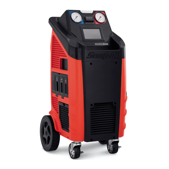
EEAC331
R134a Refrigerant
Recovery / Recycle / Recharge
Station
INTRODUCTION
Snap-on
Model No. EEAC331 is ETL Laboratories approved, in compliance with SAE J2788. We are dedicated to solving the issues
®
surrounding the safe containment and proper management of refrigerants. Your new machine incorporates the latest technology
and state of the art features to aid you in servicing R134a air conditioning and refrigeration systems. We hope you get as much
enjoyment using this equipment as we did designing and building it.
• 1 •
M A N U E E A C . 3 3 1
E D . 8
Advertisement
Table of Contents

Subscribe to Our Youtube Channel
Related Manuals for Snap-On POLARTEK PLUS EEAC331


Summary of Contents for Snap-On POLARTEK PLUS EEAC331
- Page 1 Recovery / Recycle / Recharge Station INTRODUCTION Snap-on Model No. EEAC331 is ETL Laboratories approved, in compliance with SAE J2788. We are dedicated to solving the issues ® surrounding the safe containment and proper management of refrigerants. Your new machine incorporates the latest technology and state of the art features to aid you in servicing R134a air conditioning and refrigeration systems.
- Page 2 • 2 •...
-
Page 3: Table Of Contents
ALARMS .............. 15 INDEX ERROR MESSAGES ..........16 INDEX ..............3 PRELIMINARY OPERATIONS ......17 SAFETY ..............5 AUTOMATIC PROCEDURE ......... 18 SAFETY SIGNAL WORDS ........... 5 SAFETY INFORMATION ............. 5 EDIT VACUUM DATA ............18 ... - Page 4 VACUUM PUMP ..............38 FILLING THE PAG OIL CONTAINER ........ 40 FILLING THE OIL2\DYE CONTAINER ......41 EMPTYING THE USED OIL CONTAINER ......42 REPLACING THE PRINTER PAPER ........43 INFO ..............43 WARRANTY ............44 NOTES ..............45 ...
-
Page 5: Safety
requirements also provide a basis for equipment installation, use, SAFETY and service. The following safety information is provided as guidelines to The following safety alert symbols identify important safety help you operate your new system under the safest possible messages in this manual. conditions. -
Page 6: General Safety Messages
GENERAL SAFETY MESSAGES FUME HAZARDS Warning Warning Risk of electric shock Unplug unit before attempting Risk of fume, gas, and vapor hazards maintenance or cleaning. Avoid breathing A/C refrigerant and Do not operate unit with damaged cord or lubricant vapor mist. -
Page 7: Hoses Connection
Danger REFRIGERANT AND LUBRICANT - Risk of explosion Ensure that you are only recovering from the PERSONAL PROTECTIVE EQUIPMENT fitting on the AC system. AND PRECAUTIONS Some car manufacturers on the fuel intake manifold install a connector identical to the Warning A/C low pressure fitting. -
Page 8: Setup
LANGUAGE SETUP From the SETUP, select LANGUAGE : From the MAIN MENU: R134a SETUP R134a English Français Espanol PREV AUTOMATIC MANUAL SERVICES PAGE NEXT xxxxxxx PAGE hh:mm LANGUAGE mm/dd/yyyy SETUP MAINTENANCE INFO NOTE: Current language is indicated by red dot. Select the SETUP, the following screen will be displayed: Select a language, the unit will change the language in few R134a... -
Page 9: Quicksetup
QUICKSETUP SETUP HEADER PRINT The first time the machine is used, a quick startup guide appears: The printout can be personalized by entering 4 lines containing the operator is guided through the steps described at the start of the workshop’s details (e.g. name, address, telephone number the PRELIMINARY OPERATIONS section. -
Page 10: Introduction
ABOUT YOUR AIR CONDITIONING INTRODUCTION SERVICE CENTER Snap-on Model No. EEAC331 is ETL Laboratories approved, in Your machine incorporates a highly accurate electronic scale for ® compliance with SAE J2788. We are dedicated to solving the determining charging weights, etc. Other functions can also be... -
Page 11: General Information
GENERAL INFORMATION PRINCIPLES OF OPERATION Machine model information are printed on the data plate (see In a single series of operations, the machine permits recovering Fig. 1). Overall machine dimensions: and recycling R134a refrigerant fluids with no risk of releasing the fluids into the environment, and also permits purging the A/C Height: 47"... -
Page 12: The Machine
THE MACHINE Refer to Fig. 4b. PLASTIC COVER 6) Rear body shell Refer to Fig. 4a . Disassembly: Remove rear bottom door, then screw off 1) Upper plastic body 6 screws marked (+) 2) Frontal body shell 7) Left side body shell Disassembly: Screw off 6 screws marked (+) Disassembly: Remove frontal and rear body shell, then screw off 10 screws marked (+) -
Page 13: Control Panel
DISPLAY ICONS CONTROL PANEL Refer to Fig. 5: ICON DESCRIPTION 1) Low pressure gauge AUTOMATIC PROCEDURE: Activates a menu 2) High pressure gauge that helps the user set up an automatic 3) Printer recover/vacuum/leak test/charge sequence 4) 7” touch color display MANUAL PROCEDURE: Activates a menu 5) Tool tray that helps the user to perform a manual... -
Page 14: Basic Components
BASIC COMPONENTS FIG.7 Refer to Fig. 7, Fig. 8, Fig. 9, Fig. 10: a) Handle b) Rear wheel c) Front swirling wheel d) Filter dryer panel access e) Used oil container Capsizable control panel g) Status light h) Tool tray Ventilation grid Service hoses pocket k) Oil pump filling cap... -
Page 15: Alarms
ALARMS FIG.9 HIGH PRESSURE ALARM: Beeper advises when the pressure of the fluid in the circuit is too high 290 psi (20 bar). The recovery operation is automatically interrupted. FULL TANK ALARM: Beeper advises when the tank is filled to more than 80% of maximum capacity, 24 lbs (10.9 kg). -
Page 16: Error Messages
ERROR MESSAGES CHECK CONNECTIONS: Error message displayed when the flow rate of charge is too low. SYSTEM LEAKS: Error message displayed when the AC system connections are not tight. Solution: Verify the correct opening of the quick couplers. Make sure that the amount of gas in the refrigerant tank is > 3 lbs (1.36 Solution: Verify the connections between the service hoses and kg), otherwise fill the inner refrigerant tank. -
Page 17: Preliminary Operations
PRELIMINARY OPERATIONS Check that the main switch (ref 1, Fig. 11) is set to O. Connect the machine to the electrical supply and switch on. FIG. 11 Check that the PAG oil, and OIL2/DYE containers aren’t empty, if necessary refill them as described in maintenance section. Check that the oil level in the used oil container is <... -
Page 18: Automatic Procedure
R134a AUTOMATIC PROCEDURE AUTOMATIC PROCEDURE In the automatic mode, all the operations are performed automatically: recovery and recycling, oil discharge, vacuum, The selected vacuum time is lower than 15 minutes. The leak check could not be new oil reintegration, and charging. The values for the quantity reliable. - Page 19 During the recovery phase, the machine displays the quantity of R134a AUTOMATIC PROCEDURE refrigerant recovered. Upon completion of recovery, the machine will stop and discharge, while automatically displaying Inset vehicle the used oil extracted from the A/C system during the recovery Plate number: phase.
- Page 20 R134a AUTOMATIC PROCEDURE R134a AUTOMATIC PROCEDURE Empty hoses Hoses pressure Oil Injected PAG INJECTION EMPTY HOSES When completed, the system will go on to charging with the The machine will recover the residual refrigerant into the service preset quantity of refrigerant. hoses, then the following screen will be displayed: R134a AUTOMATIC PROCEDURE...
-
Page 21: Manual Procedure
RECOVERY/RECYCLING MANUAL PROCEDURE Before the recovery, start the vehicle engine with the hood In the MANUAL PROCEDURE, all the operations can be closed (the air conditioner must switch OFF) for 10 minutes to performed individually with exception warm the engine. Switch off the vehicle engine. recovery/recycling phase, which is automatically followed by used oil discharge. -
Page 22: Vacuum
During the recovery phase, the machine displays the quantity of VACUUM refrigerant recovered. Use the quick-connect couplings to connect the hoses to the A/C Upon completion of recovery, the machine will stop and system, bearing in mind that BLUE must be connected to the low discharge, while automatically displaying the used oil extracted pressure side and RED to high pressure. - Page 23 R134a MANUAL PROCEDURE R134a MANUAL PROCEDURE Connect and open HP and LP coupling to A/C system Press ENTER End Of Procedure Vacuum time xxx min Press ENTER to continue VACUUM VACUUM Procedure is now successfully completed. Connect and open the coupling connected to the A/C system, then press ENTER to start the vacuum phase.
-
Page 24: Pag/Dye Injection
EDIT CHARGE MODE PAG/DYE INJECTION Select the connection mode: This operation can be carried out ONLY following a VACUUM HP+LP fill the refrigerant from both HP and LP service operation. ports. From the MANUAL PROCEDURE, select OIL INJECTION, the ... - Page 25 The machine will recover the residual refrigerant into the service R134a MANUAL PROCEDURE hoses, then the following screen will be displayed: R134a MANUAL PROCEDURE End Of Procedure OIL2\DYE PAG injected xxx oz OIL2\DYE xxx oz Gas charged xxx lb PAG\DYE INJECTION Press ENTER to continue The machine will continue the refilling with the preset quantity EMPTY HOSES...
-
Page 26: Charge
START PROCEDURE CHARGE After all CHARGE data is selected, press ENTER to continue, the From the MANUAL PROCEDURE, select CHARGE, the following following screen will be displayed: screen will be displayed: R134a MANUAL PROCEDURE R134a MANUAL PROCEDURE Inset vehicle Plate number: ___________________ PQRS WXYZ... -
Page 27: Services
Disconnect HP coupling. Start A/C system with LP coupling SERVICES connected, press ENTER. The A/C system will recover the refrigerant into the service hoses, The machine keeps track of the operations done on refrigerant then the following screen will be displayed: fluid: recovery, system refilling, inner bottle filling. -
Page 28: Search By Plate
SEARCH BY PLATE SEARCH BY DATE Selecting SEARCH BY PLATE, the following screen will be Selecting SEARCH BY DATE, the following screen will be displayed: displayed: R134a SERVICE ARCHIVE R134a SERVICE ARCHIVE 2016 SEARCH BY PLATE: SEARCH BY DATE: SEARCH BY PLATE: 2016 INSERT VEHICLE PLATE... -
Page 29: Extract Archive
EXTRACT ARCHIVE Selecting EXTRACT ARCHIVE, the following screen will be displayed: R134a SERVICE ARCHIVE Please insert USB key and press ENTER Insert the storage device in the USB port and press ENTER, to save to copy a .CSV file with all the operations into the USB storage device. -
Page 30: Maintenance
MAINTENANCE A/C PRESSURES CHECK From the MAIN MENU: From MAINTENANCE select A/C PRESSURES CHECK, the following screen will be displayed: R134a R134a MAINTENANCE Connect and open HP and LP coupling to A/C system Press ENTER AUTOMATIC MANUAL SERVICES xxxxxxx hh:mm mm/dd/yyyy SETUP MAINTENANCE... - Page 31 R134a MAINTENANCE A pop-up message is displayed asking confirmation, press YES to continue: R134a MAINTENANCE Empty hoses Are you sure that you have unscrewed Hoses pressure coupling or couplings without removing them? A/C PRESSURES CHECK A pop-up message is displayed asking confirmation, press YES to EMPTY HOSES continue: The machine will recover the residual refrigerant into the service...
-
Page 32: Air Purge Manual
NOTE: If there isn’t air into the tank, the following message is displayed: AIR PURGE NOT NECESSARY. Press ESC to terminate the Air Purging process, and return to the MAINTENANCE menu. CALIBRATION For assistance, call the Snap-on toll-free Technical Support Line 800-225-5786 in the continental U.S. or Canada. -
Page 33: Change Dryer Filter
R134a MAINTENANCE CHANGE DRYER FILTER Replace the filter whenever the machine gives the service alarm Verifying gas presence in filter… signals the presence of humidity in the circuit. Before performing any operation, check that the replacement filter is the same type as these installed on the machine. Then proceed as described below: CHANGE DRYER FILTER Wear protective gloves and glasses. - Page 34 FIG. 19 FIG. 18 Press ENTER to continue: And press ENTER: R134a MAINTENANCE R134a MAINTENANCE Verify that both o-rings are correctly placed into their seats press enter Continue with vacuum and check for leaks. Press ENTER CHANGE DRYER FILTER CHANGE DRYER FILTER Take the new filter, wet with clean POE oil both o-rings, and Press ENTER to continue with vacuum check: verify that they are correctly placed into their slots, press ENTER:...
-
Page 35: Database
After few minutes, if no leaks are detected the following screen will be displayed: DATABASE R134a MAINTENANCE From MAINTENANCE, select DATABASE. A list of brand of vehicle will be displayed. Select the brand of vehicle, (use the arrow keys to change page if Pressure check necessary), then select the model of vehicle. -
Page 36: Maintenance Report
MAINTENANCE REPORT TANK CELL CHECK From MAINTENANCE, select MAINTENANCE REPORT, the From MAINTENANCE, select TANK CELL CHECK, the following following screen will be displayed: screen will be displayed: R134a MAINTENANCE REPORT R134a MAINTENANCE FILTER CHANGE mm/dd/yy xx lbs mm/dd/yy xx lbs TANK CELL CHECK mm/dd/yy xx lbs... -
Page 37: Tank Filling
Press ENTER to start The TANK FILLING: TANK FILLING R134a MAINTENANCE This operation must be performed whenever the available Tank Pressure Ext. Tank Pressure refrigerant fluid in the tank is less than 6.6 lb (3 kg) and must in any case be performed when the “empty tank” alarm is displayed. -
Page 38: Vacuum Pump Oil Change
VACUUM PUMP OIL CHANGE VACUUM PUMP From MAINTENANCE, select VACUUM PUMP OIL CHANGE, the Perform the operations listed below on a routine basis in order to following screen will be displayed: ensure good operation of the vacuum pump. When replacing the pump oil, use only the oil recommended by R134a MAINTENANCE the manufacturer. - Page 39 Pour in new oil through the filling hole, using a proper funnel (ref 5, Fig. 27), until the level rises to the midpoint on the indicator (ref 3, Fig. 27). FIG. 27 FIG. 24 Unscrew the drain cap (ref 2, Fig. 25). FIG.
-
Page 40: Filling The Pag Oil Container
FILLING THE PAG OIL CONTAINER Types of oil: use only oils recommended by the manufacturer or by the car manufacturers. Always refer to the information provided by the A/C system manufacturer. Never use waste oil. Procedure: Open the upper door on the right side (ref 4, Fig. 29). Press quick connection button (ref 1, Fig. -
Page 41: Filling The Oil2\Dye Container
FILLING THE OIL2\DYE CONTAINER NOTE: Using DYE not recommended by the manufacturer will invalidate the warranty. Procedure: Open the upper door on the right side (ref 4, Fig. 32). Press quick connection button (ref 1, Fig. 32) to disconnect the OIL2\DYE container. -
Page 42: Emptying The Used Oil Container
FIG. 37 FIG. 38 TOOLS: Funn Disp osal conta iner Allen wren ch n° 5; 8. FIG. 39 • 42 •... -
Page 43: Replacing The Printer Paper
REPLACING THE PRINTER PAPER INFO Open the print cover (ref 3, Fig. 40), and replace the paper roll From the MAIN MENU: with a new one. R134a Use only heat-sensitive paper of the type described below. Paper width: 2.2 in (58 mm). Maximum paper roll diameter: 1.6 in (40 mm). -
Page 44: Warranty
WARRANTY This product is warranted against any defect in materials and/or construction for a period of 2 (two) years from the date of delivery. The warranty consists of free-of-charge replacement or repair of defective component parts or parts considered defective by the Manufacturer. Reference to the machine serial number must be included in any requests for spare parts. -
Page 45: Notes
NOTES • 45 •... - Page 46 • 46 •...
- Page 47 • 47 •...
- Page 48 Made in USA Snap-on is a trademark of Snap-on Incorporated ©2016 Snap-on Incorporated Printed in USA Snap-on, 2801 80th St., Kenosha, WI 53143 www.snapon.com • 48 •...
Need help?
Do you have a question about the POLARTEK PLUS EEAC331 and is the answer not in the manual?
Questions and answers