Table of Contents
Advertisement
Advertisement
Table of Contents
Troubleshooting

Subscribe to Our Youtube Channel
Related Manuals for Orion ORION 8004


Summary of Contents for Orion ORION 8004
-
Page 2: Table Of Contents
CONTENTS Introduction ............2 What’s in the Box . -
Page 3: Introduction
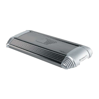
Orion amplifiers are designed as the best affordable high end car audio amplifier money can buy. Listed below are the features of the new Orion 8004. 8004 - 100 Watts per channel, four-channel amplifier with dual built-in fully vari- able high-pass, low-pass, and band-pass 12dB/octave crossovers with INTELLi Bass. -
Page 4: Warranty
WARRANTY Directed Electronics, Inc. promises to the original purchaser, to replace this product should it prove to be defective in workmanship or material under normal use, for a period of two years from the date of purchase by the dealer as indicated by the date code marking of the product PROVIDED the product was installed by an authorized Directed dealer. -
Page 5: Specifications
SPECIFICATIONS Amplifier Section Power Output 4W Stereo (Watts) Power Output 2W Stereo (Watts) Power Output 4W Mono (Watts) Remote Gain Capable Distortion - with all channels driven at rated power (20Hz to 20kHz) Frequency Response Linear Bandwidth Signal-to-Noise Ratio at Rated Power Damping Factor Slew Rate RCA Input Sensitivity... -
Page 6: Amplifier Controls And Connections
AMPLIFIER CONTROLS AND CONNECTIONS Power LED - when lit indicates that the amplifier is on. Front Low-Pass Crossover Switch - activates 2nd order low-pass crossover. Front Low-Pass Frequency Control - adjusts the frequency of the low-pass crossover. Front Gain Control - continuously adjusts from 200mV to 5V for full power output. Front RCA Inputs - accepts RCA input from a source unit, preamplifier, or equalizer. -
Page 7: Amplifier Settings
The 4CH / 2CH switch routes input from the front inputs to the rear section of the amplifi- er. This allows the Orion 8004 channel amplifier to utilize a single set of RCA's to feed sig- nal to the front and rear channels of the amplifier. -
Page 8: Fine Tuning The Crossover Frequency
Fine Tuning the Crossover Frequency The crossover section is marked at four frequency points for ease of system adjustment. These points are 20Hz, 45Hz, 250Hz, and 3kHz. Specific crossover points can be chosen based on the recommended operational bandwidth of your speakers. Remote Gain Operation The remote gain port provides easy remote access to the internal gain structure of the rear channels of the Orion power amplifier. -
Page 9: Amplifier Wiring
45Hz. Initially the Q is very low (wide). As INTELLi Bass is added, the Q rises (nar- rows). This allows the Orion 8004 to overcome acoustic deficiencies in your vehicle. The type of enclosure used, the sub-woofer's excursion capability, personal preference, and attitude determine acceptable boost levels. - Page 10 Two Channel Bridged Configuration Front and rear channels are configured for bridged two-channel operation. Lowest recommended impedance for both front and rear channels is 4W. Crossover and gain configurations are independently adjustable between the front and rear channels. Two-channel operation is recommended for this operational mode. Front and rear outputs can be configured for high-pass, low-pass, or full range operation.
- Page 11 Two-channel or four-channel input can be used for this configuration. For source unit fading, use the four-channel input mode. Front and rear outputs can be configured for high-pass, low-pass or full-range operation. Rear outputs are configured for summed bridged operation for subwoofer appli- cations.
-
Page 12: Amplifier Installation
AMPLIFIER INSTALLATION Choosing Mounting Locations The location of your amplifier will depend on several important issues. Due to the low pro- file size of the Orion amplifiers, there are many possible installation locations that will yield satisfactory amplifier performance. Always mount the amplifier in a place that protects the amplifier from the elements. -
Page 13: Tools Of The Trade
Power for systems with a single amplifier can be supplied by most automotive electrical sys- tems. Systems with multiple amplifiers may require a higher capacity battery, alternator or the use of a storage capacitor. We strongly recommend the use of a Directed Audio Essentials power capacitor with an extra battery in larger stereo systems. -
Page 14: Step By Step Installation
Step By Step Installation Step 1 Determine the location for the amplifier. Refer to the Choosing Mounting Locations section of this guide for detailed information. Step 2 Decide on the system configuration for your amplifier. For system sugges- tions, refer to the Speaker Connections section of this guide. Step 3 Run all the wires from the amplifier location to the speakers, source unit, and battery. -
Page 15: Set Up And Troubleshooting
SET UP AND TROUBLESHOOTING Testing the System After you have completed the installation, you need to test the system. This will help ensure years of trouble-free operation. Please refer to the listed steps below when testing the sound of your Orion system. Step 1 Check all the wiring connections to be sure they are correct and secure. -
Page 16: Adjusting The Sound Of The System
Adjusting the Sound of the System Once you have checked the system's operation, adjust the sound of the system. Adjusting the sound of the system is accomplished by setting the level controls and adjusting the internal crossovers. Step 1 Turn the signal source volume control all the way down. Set any tone con- trols to their flat or defeated positions. -
Page 17: Troubleshooting Tips
Troubleshooting Tips Symptom Probable Cause No output Low or no remote turn-on Fuse blown Power wires not connected Check power wire and ground Audio input not connected Check RCA connections and Speaker wires not connected Speakers are blown Audio cycles on and off Thermal protection engages when amplifier heatsink... - Page 18 Symptom Probable Cause Distorted output Internal crossover not set properly for speakers Speakers are blown Poor bass response Speakers wired with wrong Check speaker polarity and fix polarity causing cancellation as needed. at low frequencies Crossover set incorrectly Impedance load at amplifier Check speaker impedance load, is too low Battery fuse blowing...
-
Page 19: Notes
NOTES ____________________________________________________ ____________________________________________________ ____________________________________________________ ____________________________________________________ ____________________________________________________ ____________________________________________________ ____________________________________________________ ____________________________________________________ ____________________________________________________ ____________________________________________________ ____________________________________________________ ____________________________________________________ ____________________________________________________ ____________________________________________________ ____________________________________________________ ____________________________________________________ ____________________________________________________ ____________________________________________________ ____________________________________________________ ____________________________________________________ ____________________________________________________ ____________________________________________________ ____________________________________________________ ____________________________________________________ ____________________________________________________ ____________________________________________________ ____________________________________________________ ____________________________________________________ ____________________________________________________ ____________________________________________________ ____________________________________________________ ____________________________________________________ ____________________________________________________ ©2004 Directed Electronics, Inc. - Page 20 Warranty LIMITED TWO YEAR CONSUMER WARRANTY: Directed Electronics, Inc. promises to the original purchaser, to replace this product should it prove to be defective in workmanship or material under normal use, for a period of two years from the date of purchase by the dealer as indicated by the date code marking of the product PROVIDED the product was installed by an authorized Directed dealer.
Need help?
Do you have a question about the ORION 8004 and is the answer not in the manual?
Questions and answers