Table of Contents
Advertisement
Quick Links
Advertisement
Table of Contents

Related Manuals for Shuttle XPC MAX SB83G5C


Summary of Contents for Shuttle XPC MAX SB83G5C
- Page 1 XPC User Guide For the : XPC MAX SB83G5C...
- Page 2 Shuttle Mainboard EMI Test Statement Shuttle mainboards have been through EMI tests according to the following series of regulations: EN55022/CISPR22/AS/NZS3548 Class B, EN55024 (1998/AS/NZS), EN4252.1 (1994), EN61000, ANSI C63.4 (1992), CFR47 Part 15 Subpart B, and CNS13438 (1997). The items tested are illustrated as follows: (A) Voltage: AC 110V/60HZ &...
- Page 3 Panasonic SU-256A888PC, 1.44MB CD-ROM BenQ 652A-6N2, 52X Memory x2 Kingston KVR400X64C25/256, 256MB NTXC Tuner Card Shuttle PM 11 PAL Tuner Card Shuttle PM 12 Power Shuttle PC40N250EV, 250W (E) Notices for Assembling Computers: 1. An I/O shielding should be contacted with I/O metallic parts of a mainboard.
- Page 4 2. This device must accept any interference received, including interference that may cause undesired operation. Trademarks Shuttle is a registered trademark of Shuttle Inc. Intel and Pentium are registered trademarks of Intel Corporation. PS/2 is a registered trademark of IBM Corporation.
- Page 5 Read the following precautions before setting up a Shuttle XPC. CAUTION Incorrectly replacing the battery may damage this computer. Replace only with the same or equivalent as recommended by Shuttle. Dispose of used batteries according to the manufacturer's instructions. Installation Notices Do not place this device underneath heavy loads or in an unstable position.
-
Page 6: Table Of Contents
Extended USB Connectors (USB2/USB3/USB4) ........9 SPDIF-Out Connector (J2)(White) ............9 1.5 Remote Control Key Definition ..............10 1.6 Shuttle Versatile Front-panel Display (VFD) Introduction ......11 2 XPC Installation Guide ..................12 2.1 Installation ....................12 2.1.1 Remove the Cover ................12 2.1.2 Remove the Rack ................ - Page 7 2.4 Cable and Rack Installation ................ 21 2.4.1 Install the FDD Cable ................21 2.4.2 Install the IDE HDD Cable ..............22 2.4.3 Install a Serial ATA HDD Cable ............. 23 2.4.4 Install the Rack ..................24 2.5 Peripheral Installation ................. 26 2.5.1 Install the IDE HDD ................
- Page 8 4 Software Utility....................41 4.1 XPC Configuration ..................41 Media Library Configuration ................ 41 DVD Configuration ..................41 4.2 XPC MAX Interface..................41 Ten-foot Interface ..................41 4.3 Setting Up XPC MAX ................... 42 General Settings ..................42 TV Settings ....................42 Picture Settings ..................
- Page 9 INTEGRATED PERIPHERALS ..............69 POWER MANAGEMENT SETUP ..............74 PNP/PCI CONFIGURATIONS ..............78 PC HEALTH STATUS .................. 80 Frequency/Voltage Control ................82 LOAD FAIL-SAFE DEFAULTS ..............84 LOAD OPTIMIZED DEFAULTS ..............84 SET PASSWORD ..................85 SAVE & EXIT SETUP .................. 86 EXIT WITHOUT SAVING ................
-
Page 10: Function Introduction
The XPC has been designed to be easily assembled and configured directly by the end user. Consumers can choose to buy preconfigured, ready-to-run XPC’ s as well~a list of Shuttle-authorized value-added resellers can be found at www. shuttle.com. -
Page 11: Model Specifications
< 1.2 Model Specifications Form Factor Shuttle Small Form Factor Processor 533/800MHz FSB Intel Pentium 4 (LGA775) Chipset Intel 915G + ICH6-R Memory (2) 184 pin 333/400 Dual Channel DDR DIMMs 4GB capacity, Max.2GB per DIMM Audio Realtek ALC658 5.1 channel audio... -
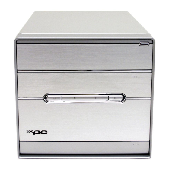
Page 12: Xpc Exterior Dissection
< 1.3 XPC Exterior Dissection Note : Shuttle offers a variety of different XPC models loaded with various options. The illustration below will help familarize you with the included features in your new XPC. < 1.3.1 XPC Front Eject button 5.25”... -
Page 13: Xpc Back
< 1.3.2 XPC Back SPDIF-out (Optical) AC power socket COM port VGA port SPDIF-in port FireWire® 400 port PS/2 Mouse PS/2 Keyboard LAN port USB ports SPDIF OUT Line-in port (Coaxial) Central/Bass Rear-out (R/L) Front-out (R/L) Clear CMOS button 17. FM in Port 18. -
Page 14: Hardware Installation
< 1.4 XPC Mainboard < 1.4.1 FB83 mainboard illustration SPDIF-Out/Line-IN Ports LAN & USB 2.0 Port LINE-IN- J4 PS/2 Keyboard/Mouse Port Center/Bass/Rear-Out/ 1394a Port Front-Out Ports SPDIF-In Port Clear CMOS Button COM & Ports Realtek ALC658 CD-IN- J1 One Floppy Connector ATX3 ATX 5V/12V Wireless KB/MS... -
Page 15: Jumper Settings
< 1.4.2 Jumper Settings Several hardware adjustments are made by setting jumpers on the mainboard. To successfully change jumper settings, you will need to locate pin#1. In this manual, pin#1 is represented by a white square, other pins are represented by a circles. An illustration is shown below for your reference: 3 2 1 Jumpers with two pins are shown as... -
Page 16: Fan Connectors (Fan1/Fan2/Fan3)
Fan Connectors (FAN1/FAN2/FAN3) This mainboard features three onboard 12V cooling fan connectors. These fans are refered to as; System (FAN1), Chipset (FAN2) or Auxillary (FAN3) cooling fans. Refer to the illustration below for more information about the fan connectors located on this mainboard. -
Page 17: Ir Connector (Jp8)
A DB25 male parallel port header is located near the rear panel of the mainboard. The header is used to connect a parallel port socket (PC8) to the mainboard. The parallel printer port can be purchased from Shuttle as an optional accessory. Pin Assignments (JP5):... -
Page 18: Extended Usb Connectors (Usb2/Usb3/Usb4)
Extended USB Connectors (USB2/USB3/USB4) These headers are used to connect auxillary USB devices to the mainboard. These headers are directional and will only allow USB cables to be connected in one direction. Pin Assignments (USB2): Pin Assignments (USB4): USB2 1=GND 1=VCC USB4 2=GND... -
Page 19: Remote Control Key Definition
< 1.5 Remote Control Key Definition Power on/off Record Stop Pause Rewind Play FastFwd Back Replay/Previous Skip/Next Select Direction (up/down/left/right) Volume up/down Home Mute on/off Channel & Page up/down Mode TV, Music, Pictures, Videos Print, DVD Menu Numeric pad: 0-9 (A~Z),#,*... -
Page 20: Shuttle Versatile Front-Panel Display (Vfd) Introduction
< 1.6 Shuttle Versatile Front-panel Display (VFD) Introduction The VFD panel included in this XPC is designed to serve as an alternative display for enhanced multimedia enjoyment. As such, the VPD panel can display; music track info, time, track time, DVD info, DVD play length, TV channel, radio stations, picture information and much more. -
Page 21: Xpc Installation Guide
2 XPC Installation Guide < 2.1 Installation Note : For safety reasons, please ensure that the power cord is disconnected before opening the case. < 2.1.1 Remove the Cover 1. Unscrew the three thumbscrews. 2. Slide the cover backwards and upwards. -
Page 22: Remove The Rack
< 2.1.2 Remove the Rack 1. Unfasten the rack mount screws. 2. Remove the rack. Rack... -
Page 23: Cpu And Ice Installation
< 2.2 CPU and ICE Installation < 2.2.1 Remove the ICE Module 1. Unfasten the ICE fan thumbscrews on the back of the chassis. 2. Unplug the fan power connector. 3. Unfasten the four attachment screws. - Page 24 4. Remove the ICE module from the chassis and put it aside. ICE Heat-Pipe Module Smart Fan Smart Fan Power Connector Heat sink...
-
Page 25: Install The Cpu
< 2.2.2 Install the CPU Note : This 775 pin socket is fragile and easily damaged. Always use extreme care when installing a CPU and limit the number of times that you remove or change the CPU. 1. Remove the protective cover. 2. - Page 26 3. Orientate the CPU and socket, aligning the yellow triangle on the corner of the CPU with the triangle on the socket. Making sure the CPU is perfectly horizontal, insert the CPU into the socket. Close the load plate, lower the CPU socket lever and lock in place. 4.
-
Page 27: Install The Ice Module
< 2.2.3 Install the ICE Module 1. Place the ICE the module on top of the CPU and align the spring loaded screws with the mainboard mounting holes. 2. Screw the ICE module to the mainboard. Note to press down on the opposite diagonal corner while tightening each screw. -
Page 28: Ddr Installation
4. Fasten the Smart Fan to the chassis with the four thumbscrews. < 2.3 DDR Installation Memory Compatibility : Install memory in any or all of the banks according to the combinations shown below. TOTAL 2 DIMM in Single or Dual Channel Mode up to 4GB and 2GB per DIMM Density 256 Mbit... - Page 29 Install a DDR module in DIMM1/DIMM2. 1. Unlock the DIMM latch. 2. Align the DDR module's cutout with the DIMM slot notch. Slide the DDR module into the DIMM slot. Cutout Notch Latch Latch Check that the latches are closed, and the DDR module is firmly installed.
-
Page 30: Cable And Rack Installation
< 2.4 Cable and Rack Installation < 2.4.1 Install the FDD Cable Note : If you do not wish to install a FDD, proceed to step 2.4.2. Pin1 (white line) 1. Plug the FDD cable in the FDD header (FDD1). 2. -
Page 31: Install The Ide Hdd Cable
Note : Only complete section 2.4.2 if you wish to install a IDE hard drive. If you do not wish to install an IDE hard drive, proceed to section 2.4.3. < 2.4.2 Install the IDE HDD Cable 1. Remove the IDE cable. IDE (Optical drive) cable 2. -
Page 32: Install A Serial Ata Hdd Cable
3. Loosen the purse lock and separate the IDE HDD/FDD power cable (white). IDE HDD & FDD Power Connector < 2.4.3 Install a Serial ATA HDD Cable Note : Only complete this step if you will install two Serial ATA HDDs. 1. -
Page 33: Install The Rack
2. Loosen the purse lock and separate the FDD power cable (white) and Serial ATA HDD power cable (black). FDD Power Cable Serial ATA Power Cable < 2.4.4 Install the Rack 1. Place the HDD in the rack and secure with screws from the side. Screws (HDD) Note : Secure with two screws on each side. - Page 34 Note : Refer to section 2.4.4-3A if installing an IDE HDD. Refer to section 2.4.4-3B if installing a Serial ATA HDD. 3A. Place the IDE HDD and power cables in the rack clip located on the underside of the rack mount. Rack Clip 3B.
-
Page 35: Peripheral Installation
5. Refasten the rack. < 2.5 Peripheral Installation Note : Refer to section 2.5.1 if installing an IDE HDD. Refer to section 2.5.2 if installing a Serial ATA HDD. < 2.5.1 Install the IDE HDD 1. Connect the HDD power and IDE cables to the HDD. -
Page 36: Install The Serial Ata Hdd
< 2.5.2 Install the Serial ATA HDD 1. Connect the Serial ATA and power cables to the HDD. Serial ATA Power Cable Serial ATA Cable < 2.5.3 Install the Floppy Drive 1. Connect the FDD and power cables to the Floppy drive. FDD Cable FDD Power Cable <... - Page 37 2. Open the stealth drive door. Check the alignment of the drive's eject button with this XPC's drive eject mechanism. Press the external eject button to check. If it is well aligned, proceed Step 8. If it is poorly aligned, adjust the internal control rod to suite. Adjust Control rod Note : After adjusting the position of the control rod you may find that it still does not align well with the eject button.
- Page 38 5. Remove the 1.2 mm control rod. 1.8 mm 1.2 mm 6. Take out the 1.8 mm control rod from the accessory box and insert it in the slot as show. 7. Connect the USB cable. Reattach the front panel. Check the alignment and adjust if necessary.
- Page 39 . Plug the optical drive cable and power cable into the optical drive. Optical Drive Cable Optical Drive Power Cable Note : If you are installing an IDE HDD, use the same cable for the HDD and the optical drive. 9.
-
Page 40: Accessories Installation
< 2.6 Accessories Installation < 2.6.1 Install PCI Express Card 1. A PCI Express VGA card will be used to demonstrate this installation procedure. PCI Express card Unfasten the expansion slot bracket screws. PCI Express slot Remove the back panel bracket and put the bracket aside. Lift up Slot Bracket... - Page 41 4. Install the PCI Express VGA card into the PCI Express slot. 5. Secure the bracket.
-
Page 42: Final Touches
< 2.7 Final Touches < 2.7.1 Close the Chassis Cover 1. Replace the cover and refasten the thumbscrews. < 2.7.2 Install Front Feet 1. Take out the two front feet from the accessory box. Front feet 2. Screw the front feet to the base of the chassis. -
Page 43: Complete
< 2.7.3 Complete < 2.8 XPC Accessories Shuttle offers over 25 great upgrade and modding kits for your XPC. Visit our website at http://www.shuttle.com for more information or speak to your local retailer. < 2.9 Tech Support Shuttle Inc. http://www.shuttle.com Tech Support http://global.shuttle.com/Support/Support.asp... -
Page 44: A Technical Notes: Clear Cmos Button
< 2.A Technical Notes: Clear CMOS Button This XPC comes enhanced with an easy-to-use Clear CMOS Button. This button allows users to reset BIOS information to factory default settings. 1. Power down the XPC and remove the power cord. 2. Press the Clear CMOS Button by inserting a pointed object (e.g. a pen nib) into the clear CMOS hole. -
Page 45: Tv Signal Cable
TV signal cable: Connect the TV (antenna/cable TV) cable to the protruding TV RF-in jack. TV RF-in jack Note : XPC MAX TV features will only operate if your TV signal cable (antenna or cable TV) is connected. Multi-function Audio/Video port : Note : This cable connects the XPC to a video casette recorder (VCR). -
Page 46: Driver And Software Installation
DirectX9 Utility. Install Utility - Install Acrobat Reader, WinFlash Utility, XPC Tools. Manual - XPC MAX SB83G5C user's guide in PDF format. Link to Shuttle Homepage - Link to shuttle website homepage. Browse this CD - Allows you to see contents of this CD. -
Page 47: Install Mainboard Software
Insert the attached CD into your CD-ROM drive. The CD AutoRun screen should appear. If the AutoRun screen does not appear, double click on Autorun icon in My Computer to bring up Shuttle Mainb-oard Software Setup screen. Click the “Install Main-board Software“ bar. Individually install the following drivers. -
Page 48: Install Xpc Tools Software
< 3.2 XPC Tools Software Created especially for the XPC, XPC Tools includes many useful features to allow you to manage and control your system from the comfort of your Windows operating environment. Included in this version of XPC Tools are features to allow you to: 1. -
Page 49: Install Xpc Max Software
< 3.3 Install XPC MAX Software To install XPC MAX, insert the XPC drivers CD into your CD-ROM drive and the CD AutoRun screen should appear. If the Auto Run screen does not appear, double click or run D:\Autorun. exe (assuming that your CD-ROM drive is drive D:). 1. -
Page 50: Software Utility
4 Software Utility < 4.1 XPC MAX Configuration Media Library Configuration XPC MAX lets you set up your own media library. In this configuration, you can have four libraries for different file types: video, music, picture and playlist. Each library contains and lists paths that you add. -
Page 51: Setting Up Xpc Max
< 4 . 3 Setting up XPC MAX General Settings Hide Date & Time : You can decide whether to hide the date & time shown on the top bar of the interface. To hide date & time, select the Yes Markers checkbox; to show date & time, select the No Markers checkbox. -
Page 52: Picture Settings
Picture Settings Configuring your Picture settings gives you total control over the way you view your pictures. Transition Time : Change duration of the transition for a slide show. Play in Random Order : Choose whether to view your pictures in random order. Select Yes or No checkbox. -
Page 53: Using Xpc Max
< 4.4 Using XPC MAX TV Mode Watching TV using XPC MAX provides full screen video in an easy to control environment. With XPC MAX, you can schedule your favorite shows and movies for viewing or recording. XPC MAX also supports TV time shifting, meaning you can pause Live TV and then con- tinue watching without missing a beat. - Page 54 This EPG lets you search for your favorite shows and quickly and easily schedule programs for viewing or recording. (EPG website varies by region. In US, it is TitanTV) Closed caption is a service providing subtitles if available. TeleText is a service for information like commertial, weather or program schedule if available.
-
Page 55: Play Dvd/Vcd
Note : Time Shifting records live TV and saves it temporarily on your hard disc, starting from when you click Pause. The Slide bar on the Player Panel indicates how much video you have recorded. Time Shifting The Time Shifting feature allows you to pause and then replay the live TV. Time Shifting gives you absolute control over how you watch television. - Page 56 XPC MAX includes several options to enhance your DVD/VCD experience: Menu leads you back to the main menu of the DVD that you are watching. You can view menu at anytime while watching DVD. If your DVD supports multiple audio language, you can select by simply clicking on Audio bar.
-
Page 57: Pictures Mode
Picture Mode XPC MAX lets you view your pictures, wallpaper, and other graphics stored on your computer, quickly and easily. Your pictures are shown in thumbnails with file name, so you can easily find which graphic you want to select. By default, when you enter Picture mode, XPC MAX will load in pictures stored in My Pictures >... -
Page 58: Slide Show
Select the pictures you want to play in slide show, and then click Play Slideshow bar to enjoy your slide show. If no pictures are selected, the silde show will play all images contained in the appointed folder. Sort your pictures based on the image file name. Sort your pictures based on the date they were created. -
Page 59: Play Video Clips
Play Video Clips Viewing video clips with XPC MAX provides full screen and high quality playback. You can select which video clip you want to view by clicking on the video thumbnail. Each video cilp is shown as thumbnail, which provides easy selection. By default, Video Clips mode will load video clips stored in My Documents >... -
Page 60: Music Mode
XPC MAX includes certain features to enhance your video clip viewing experience: Sort your video clips based on the video file name. Sort your video clips based on the date they were created. In addition to the video clips from Media Library, you can also watch video files in Shared Video and other removable devices attached to your computer. -
Page 61: Listening To Music
Listening to Music XPC MAX include cool features to enhance your audio experience and to suit your music style. Prev Volume Down Pause Fast Backward Record Mute Stop Fast Forward Play Next Volume Up This first time you enter Music mode, it will scan music from the Media Library automatically. -
Page 62: Playlist
To listen to music : Double-click on the music list or item that you want to listen to. Click the Play button in the Control Panel. With XPC MAX you can also: P Repeat : Listen to your selected music repeatedly. P Shuffle : Listen to your selected music in random order. -
Page 63: Listening To Radio
To delete songs from a playlist : Once a playlist has been saved it will exist forever. You can only temporarily delete songs from the playlist, rearrange the content of playlist and save it as another playlist. 1. From Music mode page, click Go to Playlist bar. 2. - Page 64 Play Radio Scan Down Volume Down Tune Down Mute Record Radio Tune Up Scan Up Volume Up You can save your favorite stations from the My Station list. Click on My Favorite bar, it will lead you to your Favorite Station List page where all your favorite stations added are listed here.
-
Page 65: Appendix
Appendix BIOS Settings The FB83 BIOS ROM has a built-in Setup program that allows users to modify basic system configuration. This information is stored in battery-backed RAM so that it re- tains Setup information even if the system power is turned off. The system BIOS manages and executes a variety of hardware related functions including: System date and time... -
Page 66: The Main Menu
The Main Menu Once you enter the AwardBIOS(tm) CMOS Setup Utility, the Main Menu will appear on the screen. The Main Menu allows you to select from sev- eral setup functions and two exit choices. Use the arrow keys to select among the items and press <Enter>... - Page 67 PC Health Status This entry displays the current system temperature, Voltage, and FAN settings. Frequency/Voltage Control Use this menu to specify your settings for frequency/voltage control. Load Fail-Safe Defaults Use this menu to load the BIOS default values for the minimal/stable per- formance of your system to operate.
-
Page 68: Standard Cmos Features
Standard CMOS Features The items in the Standard CMOS Setup Menu are divided into several categories. Each category includes none, one or more than one setup items. Use the arrow keys to highlight the item and then use the <PgUp> or <PgDn>... - Page 69 Halt On Select the situation in which you want the BIOS to stop the POST process and notify you. Ø The choice: All Errors, No Errors, All, But Keyboard, or All, But Diskette, All, But Disk/Key. Base Memory Displays the amount of conventional memory detected during boot up. Ø...
- Page 70 Capacity Disk drive capacity (Approximated). Note that this size is usually slightly greater than the size of a formatted disk given by a disk checking program. Ø Auto-Display your disk drive size. The following options are selectable only if the 'IDE Primary Master' item is set to 'Manual', and Access mode set to CHS.
-
Page 71: Advanced Bios Features
Advanced BIOS Features This section allows you to configure your system for basic operation. You have the opportunity to select the system's default speed, boot-up sequence, keyboard operation, shadowing, and security. CPU Feature Options are in its sub-menu. Press <Enter> to enter the sub-menu of detailed options. Delay Prior to Thermal This item is select Delay Prior to Thermal. - Page 72 TM2 Bus VID Represents the voltageof the throttled performance statethat will be initi- ated when the on diesensor gose from not hot to hot. Ø The Choice: 0.8375V ~1.6000V. Note: CPU support TM2, item appear. Limit CPUID MaxVal Set Limit CPUID MaxVal to 3,Should Be "Disabled" for WinXp. Ø...
- Page 73 CPU L1&L2&L3 Cache All processors that can be installed in this mainboard use internal level1 (L1) , external 2(L2) and (L3) cache memory to imporve performance. Leave this item at the default value for better performance. Ø The choice: Enabled or Disabled. Note : CPU support, L3 item appear.
- Page 74 Gate A20 Option This entry allows you to select how the Gate A20 is handled. The gate A20 is a device used for above 1MByte of address memory. Initially, the gate A20 was handled via a pin on the keyboard. Today, while a key- board still provides this support, it is more common and much faster in setting to fast for the system chipset to provide support for gate A20.
- Page 75 APIC Mode Via the routing, I/O APIC support a total of 24 interrupts. We recommend to choose [Enabled] for Windows XP and Windows 2000. Ø The choice: Enabled or Disabled. MPS Version Control For OS Selects the operating system multiprocessor support version. Ø...
-
Page 76: Advanced Chipset Features
Advanced Chipset Features This section allows you to configure the system based on the specific features of the installed chipset. This chipset manages bus speeds and access to sys- tem memory resources, such as DRAM and the external cache. It also coor- dinates communications between the conventional ISA bus and the PCI bus. - Page 77 als that need to use this area of system memory usually discusses their memory requirements. Ø The Choice: Enabled or Disabled. ********** VGA Setting ********** PEG/Onchip VGA Control This item allows you to decide to activate whether PEG slot or Onchip VGA first.
-
Page 78: Integrated Peripherals
Integrated Peripherals On-Chip IDE Device Option are in its sub-menu. Press<Enter>to enter the sub-menu of detailed options. IDE HDD Block Mode If your IDE hard disk drive supports block mode (most new drives do), select Enabled to automatic detect the optimal number of block read and writes per sector that the drive can support and improves the speed of access to IDE devices. - Page 79 IDE Primary Master/Slave UDMA Each IDE channel supports a master device and a slave device. This mainboard supports UltraDMA technology, which provides faster access to IDE devices. If you install a device that supports UltraDMA, change the appropriate item on this list to Auto. You may have to install the UltraDMA driver supplied with this mainboard in order to use an UltraDMA device.
- Page 80 Enhanced Mode: Enables both SATA and PATA. Max. 2 ATA drives are supported. Some current operationg systems (WinXP,Windows NET Server,Windows2000) support Enhanced mode. Serial ATA 1 (Channel 1) Master Serial ATA 2 Master (Channel 2) IDE1 (Channel 0) Master Slave SATA-Only :SATA operates in legacy mode.
- Page 81 SATA Hot-Plug This item allows you to set the SATA Hot-Plug. Ø The choice: Disabled or Enabled. Onboard Device Option are in its sub-menu. Press<Enter>to enter the sub-menu of detailed options. USB Controller Select Enabled if your system contains a Universal Serial Bus (USB) port on this mainboard.
- Page 82 Onboard Infrared Port This option is used to assign the I/O address and interrupt request ( IRQ ) for the onboard infrared port. Ø The choice: Disabled, 3F8/IRQ4, 2F8/IRQ3, 3E8/IRQ4, 2E8/IRQ3 or Auto. UART Mode Select This field is available if the Onboard Serial Port 2 field is set to any option but disabled.
-
Page 83: Power Management Setup
Power Management Setup The Power Management Setup allows you to configure your system to most effectively save energy while operating in a manner consistent with your computer usage. ACPI Function This item allows you to enable/disable the Advanced Configuration and Power Management (ACPI). - Page 84 V/H SYNC+Blank This selection will cause the system to turn off the vertical and horizontal synchronization ports and write blanks to the video buffer. Blank Screen This option only writes blanks to the video buffer. DPMS Initial display power management signaling. Ø...
- Page 85 Wake-Up by PCI card This item Enabled/Disabled PCI Power Management Event to wake up system. Ø The choice: Enabled or Disabled. Power On by Ring This item determine the system will resume by activating of modem ring. Ø The choice: Enabled or Disabled. USB KB/MS Wake-up From S3 If you are using a USB KB/MS, and the ACPI suspend type is set to S3, you can enable this item to allow a KB/MS to wake up the system from power...
- Page 86 FDD, COM, LPT Port When this item is enabled, the system will restart the power-saving timeout counters when any activity is detected on the floppy disk drive, serial ports, or the parallel port. Ø The choice: Disabled or Enabled. PCI PIRQ [A-D] # When this item is disabled, any PCI device set as the Master will not power on the system.
-
Page 87: Pnp/Pci Configurations
PnP/PCI Configurations This section describes the configuration of PCI bus system. PCI or Per- sonal Computer Interconnection is a system which allows I/O devices to operate at the speed CPU itself keeps when CPU communicating with its own special components. This section covers some very technical items, and it is strongly recom- mended that only experienced users should make any changes to the default settings. - Page 88 If you set this field to "manual" , choose specific resources by going into each of the sub-menu that follows this field (a sub-menu is proceeded by a ">"). Ø The choice: Auto(ESCD) or Manual. IRQ Resources When resources are controlled manually, assign each system interrupt a type, depending on the type of device using the interrupt.
-
Page 89: Pc Health Status
PC Health Status CPU Fan Speed Control Here you can set the ICE Fan Speed. Ø The choice: Smart Fan, Ultra-Low, Low , Mid , or Full . Note : Before manually modifying the CPU fan setting, please make sure fan connectors are plug ged into the correct fan connector on the mainboard. - Page 90 CPU Temp Tag This item is only for Shuttle's unique 'Smart Fan' temperature control program.Temp tag lets you specifiy your optimal CPU temperature, then 'Smart Fan' takes over and controls the fan rpm accordingly. Choose a temperature setting between 25...
-
Page 91: Frequency/Voltage Control
Frequency/Voltage Control Auto Detect PCI Clk This item allows you to auto enable/disable an empty PCI Slot Clock. Ø The choice: Enabled or Disabled. Spread Spectrum This item allows you to enable or disable the spread spectrum modulation. Ø The choice: Disabled or Enabled. DRAM Timing Selectable The value in this field depends on performance parameters of the installed memory chips(DRAM). - Page 92 signals when DRAM is written to, read from, or refreshed. Faster perfor- mance is gained at high speed, more stable performance, at low speed. This field is applied only when synchronous DRAM is installed in the system. Ø The Choice: Auto, 5, 4, 3 or 2. DRAM RAS # Precharge If an insufficient number of cycles is allowed for the RAS to accumulate its charge before DRAM refresh, the refresh may not complete, and the DRAM...
-
Page 93: Load Fail-Safe Defaults
CPU Clock This item allows the user to adjust CPU Host Clock. Min: 100 Max: 355 Ø Key in a DEC number: (Between Min and Max.) ****** Voltage ****** CPU Voltage This item allows you to set CPU Voltage. Ø The choice: 0.825V~1.5875V or Auto. DDR Voltage This item allows you to set DDR Voltage. -
Page 94: Set Password
Set Password This item is to set a supervisor password. Please follow below steps. New Password Setting: 1. Press the <Enter> key. A dialog box appears to ask you to “Enter password: “. 2. Key in a new password. The password can not be over eight characters or numbers. 3. -
Page 95: Save & Exit Setup
Save & Exit Setup Press <Enter> on this item to save your changes. The system will ask for confirmation : system Save to CMOS and EXIT (Y/N)? Y Pressing "Y" stores the selections made in the menus of CMOS - a special section of memory that stays on after you turn your system off.
Need help?
Do you have a question about the XPC MAX SB83G5C and is the answer not in the manual?
Questions and answers