
Related Manuals for MEN NL34


Summary of Contents for MEN NL34
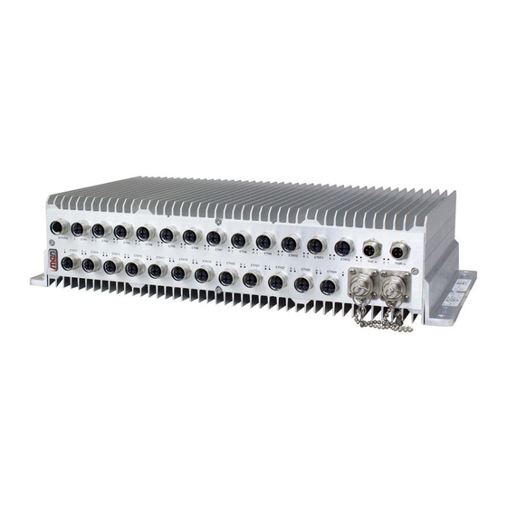
- Page 1 20NL34-00 E2 2018-02-26 NL34 Robust 24-Port Fully Managed Ethernet Switch with PoE Layer 2/3 Switch with M12 Front Connectors & Fiber Option User Manual...
-
Page 2: Table Of Contents
Unpacking the NL34 ........ - Page 3 Contents Status LEDs ............36 4 Switch Firmware .
-
Page 4: About This Document
This document is intended only for system developers and integrators. It describes the design, functions and connection of the product. The manual does not include detailed information on individual components (data sheets etc.). NL34 product page with up-to-date information and downloads: www.men.de/products/nl34/ History... - Page 5 About this Document Conventions Indicates important information or warnings concerning situations which could result in personal injury, or damage or destruction of the component. Indicates important information concerning electrostatic discharge which could result in damage or destruction of the component. Indicates important information or warnings concerning proper functionality of the product described in this document.
-
Page 6: Product Safety
Only store the product in its original ESD-protected packaging. Retain the original packaging in case you need to return the product to MEN for repair. Qualified Personnel The product/system described in this documentation may be operated only by personnel qualified for the specific task in accordance with the relevant documentation, in particular its warning notices and safety instructions. -
Page 7: Product Compliance
Technical Data and thus enable you to achieve certification of the product according to the standards applicable in your field of application. If the product delivered was certified by MEN and is modified by the customer, e.g., by installing an additional hardware component, the certification achieved by MEN becomes invalid and has to be repeated for the new product configuration. -
Page 8: Disclaimer
MEN was negligent regarding the design or manufacture of the part. In no case is MEN liable for the correct function of the technical installation where MEN products are a part of. -
Page 9: Contacts
860 Penllyn Blue Bell Pike Room 1215, #993 West Nanjing Road Blue Bell, PA 19422 Shanghai 200041 Phone 215-542-9575 Phone +86-21-5058-0963 sales@menmicro.com info@men-china.cn www.menmicro.com www.men-china.cn Copyright © 2019 MEN Mikro Elektronik GmbH. All rights reserved. 20NL34-00 E2 2018-02-26 Page 9 ... -
Page 10: Product Overview
Flexible Concept in a Small Housing The NL34 is a 24+2-port fully managed layer 2/3 Ethernet switch, providing a wide range of configuration options with 24 M12 Gigabit Ethernet ports. M12 connectors can be configured to be A-, D- or X-coded and combinations are also possible. -
Page 11: Product Architecture
Product Overview Product Architecture 1.2.1 Interfaces Figure 1. Front interfaces Power over Ethernet Console Port Gigabit Ethernet PoE Power (RS232) with Status LEDs Power Status LED Status LED (Power) Switch Opera on Gigabit Ethernet Fiber Uplink Fiber Uplink (op onal) (op onal) with Status LEDs ETH25... -
Page 12: Functions
Product Overview 1.2.2 Functions Figure 2. Functional diagram PoE+ 12x Gigabit Ethernet Vitesse Ethernet PHY 51 LEDs 1000BASE‐SX 1000BASE‐SX Vitesse UART Ethernet Switch PoE+ 10x Gigabit Ethernet Gigabit Ethernet Bypass Gigabit Ethernet Relay PoE+ PoE Power in PoE PSU Power in F Front Options 20NL34-00 E2 2018-02-26 Page 12 ... -
Page 13: Technical Data
Command line interface (CLI) via console, SSHv2, Telnet Web interface (HTTP/HTTPS) via IPv4, IPv6 See the firmware product page for more information on the switch firmware features: www.men.de/software/14etsw-02/ Power Over Ethernet PSE (Power Sourcing Equipment) Supply classes 0, 1, 2, 3, 4 ... - Page 14 24x 10/100/1000BASE-T, M12, A-coded, receptacle 22x 10/100BASE-T, M12, D-coded, receptacle 2x 10/100/1000BASE-T, M12, A-coded, receptacle D-coded connectors are typically combined with two A-coded connectors for uplink. Please contact MEN sales for component combination possibilities. Serial 1x RS232, M12, A-coded, receptacle ...
- Page 15 Product Overview Product Compliance: Rail - Rolling Stock Operating temperature: -40 °C to +70 °C, +85 °C for 10 min (EN 50155:2017, class OT4, ST1) Storage temperature: -40 °C (EN 50155:2017) to +85 °C (EN 60068-2-2, Bb) Pollution degree: EN 50124-1:2017, class PD2 ...
-
Page 16: Cooling Concept
Product Identification MEN documentation may describe several different models and design revisions of the NL34. You can find the article number, design revision and serial number affixed to the NL34. Article number: Indicates the product family and model. This is also MEN’s main ... -
Page 17: Getting Started
Before installing the NL34, make sure that the installation site has been prepared and that the operating environment meets the equipment requirements. The NL34 network box has been designed to either sit on a flat surface or be securely mounted to a wall or similar surface. -
Page 18: Safety Instructions For Mounting
Secure the M5 pan-head screws at the marked location, making sure to leave at least the following gap between the surface and the screw head: 5 mm » Place the NL34 so that the wide openings of the mounting holes are over the screw heads (1). 20NL34-00 E2 2018-02-26 Page 18 ... -
Page 19: Connecting And Starting
Connecting and Starting 2.3.1 Safety Instructions for Connection Adhere to the following safety instructions before you connect the NL34: Works on the computer system may only be carried out by personnel qualified for the specific task, who, based on their training and experience, are able to identify risks and avoid potential hazards when working with these products/systems. -
Page 20: Connecting An Earthing Cable
Getting Started 2.3.2 Connecting an Earthing Cable The NL34 features an earthing connection. Connect the earthing cable before making any other connections! A protective earth connection is essential for the system to meet its EMC specifications. When disassembling the system, always detach the earthing cable last. -
Page 21: Connecting The Power Supply
PoE in 12 A T When using the NL34 under full load, a power supply cable with a cross sec- tion of at least 4 mm² must be used. After connecting the power supply, the switch will boot up with its default settings. -
Page 22: Accessing The Ethernet Switch
Getting Started Accessing the Ethernet Switch 2.4.1 Web Interface The web interface provides an online help option for all configuration sheets which can be accessed by clicking on the question mark in the top right corner of the screen: Figure 5. Accessing the help option 2.4.2 Command Line Interface (CLI) -
Page 23: Configuring Basic Switch Settings
Getting Started Example of a command line interface: Username: admin Password: alarm alarm clear Clear/Reset functions configure Enter configuration mode copy Copy from source to destination delete Delete one file in flash: file system Directory of all files in flash: file system disable Turn off privileged commands To run exec commands in the configuration mode... -
Page 24: Resetting The Configuration To Factory Defaults
Getting Started 2.5.1 Resetting the Configuration to Factory Defaults » Press <Enter> until the Username: prompt appears. » Log in as admin, without entering a password: Username: admin Password: » Reload the default values: reload defaults % Reloading defaults. Please stand by. When the prompt returns, the system has reverted to factory defaults. -
Page 25: Setting The Vlan 1 Ip Address
Getting Started 2.5.4 Setting the VLAN 1 IP Address Assign an IP address to the device on VLAN 1, which is normally sufficient for small local area networks that use Dynamic Host Configuration Protocol, DHCP, or static IP address allocation. Note: IP addresses can only be assigned to VLAN interfaces. -
Page 26: Displaying And Saving The Configuration
Getting Started 2.5.5 Displaying and Saving the Configuration You can display the current configuration of the device in the form of a virtual file called running-config which contains the full set of commands necessary to create an identical configuration. The file sequence is as follows: hostname command ... - Page 27 Getting Started All interfaces except GigabitEthernet 1/1 (switch 1, port 1) are set to default, so nothing is displayed for them. Generally only the non-default configuration is displayed. » Save the configuration to the startup-config file: my-device# copy running-config startup-config Building configuration...
-
Page 28: Functional Description
Input current: 18 A max. MEN’s PU28 delivers 500 W PoE power. This increases the total available PoE power to 590 W (load sharing with internal PoE power supply). Note: Define the total available PoE power in the switch firmware. -
Page 29: Isolation Voltages
Functional Description Table 4. Connector types – 5-pin, M12, L-coded Connector Type On NL34 5-pin plug e.g., Phoenix Contact SACC-CI-M12MSL-4FE-L180 THR GR Mating 5-pin receptacle Table 5. Pin assignment - power supply (5-pin M12 L-coded) PWR_IN PWR_GND PWR_GND PWR_IN Table 6. -
Page 30: Ethernet
3.3.1.1 Fast Ethernet D-Coded Note: If the NL34 is equipped with D-coded Ethernet connectors, there are always two A-coded connectors to allow gigabit uplink: Figure 1, Front interfaces on page 11 for the position of the connectors. -
Page 31: Table 12. Connector Types - Ethernet (8-Pin M12)
3.3.1.2 Gigabit Ethernet A-Coded Table 12. Connector types – Ethernet (8-pin M12) Connector Type On NL34 8-pin M12 receptacle A-coded e.g., CONEC SAL-12-IKHW8/A6090 Mating 8-pin M12 plug A-coded e.g., Harting Electronics 21 03 821 1830 Note: For railway rolling stock installation, the mating connector must be an approved crimp connector. -
Page 32: Table 15. Connector Types - Ethernet M12
3.3.1.3 Gigabit Ethernet X-Coded Table 15. Connector types – Ethernet M12 Connector Type On NL34 8-pin M12 receptacle, X-coded e.g., Conec SAL - 12X - IKW8 Mating 8-pin M12 plug, X-coded e.g. Harting Electronics 21 03 881 1830 Note: For railway rolling stock installation, the mating connector must be an approved crimp connector. -
Page 33: Table 18. Connector Types - Q-Odc
Functional Description 3.3.1.4 Q-ODC (optional) The NL34 supports: Wire speed: ETH25: 1 Gbit/s ETH26: 1 Gbit/s (up to 2.5 Gbit/s) Figure 1, Front interfaces on page 11 for the position of the connectors. Table 18. Connector types – Q-ODC... -
Page 34: Power Over Ethernet (Poe)
Functional Description 3.3.2 Power over Ethernet (PoE) Power over Ethernet startup behavior is controlled by management firmware. Table 21. Power over Ethernet classes Guaranteed Power Guaranteed Power Class at PD Input at PSE Output 0.44 W to 12.96 W 15.4 W 0.44 W to 3.84 W 4.0 W 3.84 W to 6.49 W... -
Page 35: Rs232 (Console)
Functional Description RS232 (Console) The NL34 supports: Local system management via serial console (RS232). Configuration and maintenance. An external dongle can also be connected to the service port for switch con- figuration. Chapter 2.4.2 Command Line Interface (CLI) on page 22 for connection parameters. -
Page 36: Status Leds
Functional Description Status LEDs Table 27. General status LEDs at front panel Appearance Label Color Function Green Indicates power status On: Supply voltage is available Off: Supply voltage is not available Yellow Indicates switch operation On: Switch is operating normally ... -
Page 37: Switch Firmware
Switch Firmware Switch Firmware The NL34 is controlled via the switch firmware. No additional software is required. See the switch firmware user manual: www.men.de/products/nl34/#doc 20NL34-00 E2 2018-02-26 Page 37 ... -
Page 38: Maintenance
Maintenance Maintenance Cleaning Clean the NL34 once a year. Remove light dirt with a dry cloth. Remove persistent dirt only with a mild detergent and a soft cloth. » Remove dirt and dust from the cooling fins. Take care that no liquid gets inside the NL34 and the labels are not damaged.
Need help?
Do you have a question about the NL34 and is the answer not in the manual?
Questions and answers