
Related Manuals for Kobelt 7173-KAS

Summary of Contents for Kobelt 7173-KAS
- Page 1 8238-129 Street, Surrey, B.C. Canada V3W 0A6 Telephone 604-572-3935 Fax 604-590-8313 http://www.kobelt.com 7173-KAS MANUAL February 2012 “Leaders in Quality Marine Controls, Steering Gear, and Disc Brakes.”...
-
Page 2: Table Of Contents
MODEL 7173-KAS INSTRUCTION MANUAL CONTENTS MODEL 7173-KAS ELECTRONIC FFU STEERING SYSTEM MODEL 7173-KAS COMPONENTS MOUNTING THE 7173-KAS AMPLIFIER UNIT MOUNTING THE FFU CONTROLLER UNITS MOUNTING THE MODEL 7174 RUDDER FEEDBACK UNIT WIRING THE SYSTEM TESTING THE SYSTEM TROUBLESHOOTING PERIODIC INSPECTION... - Page 3 SELECTING AND INSTALLING ELECTRONIC REMOTE STEERING CONTROL When a full follow-up remote electronic control becomes integrated with either a manual steering system (helm pump) or a jog lever, the full follow-up control must be de-energized before putting the manual steering devices or jog levers into service.
-
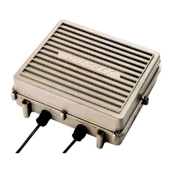
Page 4: Model 7173-Kas Components
7171, 7172, 7176, 7196 7197 and 7198 and coordinates the desired rudder position with our Also the 7173-KAS provides a pump on demand feedback unit Models 7168 or 7174. Fluid flow pilot signal (12 or 24 VDC) that can control a... - Page 5 MODEL 7173-KAS Dimensions are in inches (mm) TYPICAL MULTIPLE STATION ARRANGEMENT...
-
Page 6: Mounting The 7173-Kas Amplifier Unit
3. Follow-up (Rudder Feedback) Unit 4. Solenoid Interface Valve The Model 7173-KAS System is used to set the position (or the angle) to which the Rudder goes. The Amplifier Unit compares the respective command and feedback signals from the Controller and Follow-Up Unit. -
Page 7: Mounting The Model 7174 Rudder Feedback Unit
MOUNTING THE MODEL 7174 RUDDER FEEDBACK UNIT The Model 7174 or 7168 Follow-Up (Rudder Feedback Unit) must be mounted near the steering gear as shown in the diagram below. The output signals will then be calibrated with the tiller in place. -
Page 8: Wiring The System
The input power to the Model 7173-KAS Amplifier Unit is 11 VDC to 28 VDC. The power cable (2-conductor, #14-gauge) should be run from the switchboard through a customer-supplied on/off switch via a circuit breaker or fuse (8 amp). -
Page 9: Testing The System
Also, rudder limit adjustment can be achieved by adjusting rudder limit trim pots on 7173-KAS board or by adjusting the stroke on the feedback unit. NOTE: You must not allow the cylinder to continually push against the mechanical stops (hardover position). -
Page 10: Troubleshooting
L3 and L4 continuously ON – U2 damaged - replace If “L5” LED light is ON, then the “Alarm Output” will be active to indicate control or feedback potentiometer failure or wire break. The 7173-KAS will fail in mode upon potentiometer or wire break failure. -
Page 11: Periodic Inspection
Some Kobelt components are equipped with inspection covers which can be removed for examination of internal parts. The following serves as a general inspection guideline for Kobelt engine control and steering control system components. All deficiencies have to be fixed and defective parts be replaced by a certified technician to ensure a reliable and safe operation.
Need help?
Do you have a question about the 7173-KAS and is the answer not in the manual?
Questions and answers