
Related Manuals for Kobelt 7173-K

Summary of Contents for Kobelt 7173-K
- Page 1 8238-129 Street, Surrey, B.C. Canada V3W 0A6 Telephone 604-572-3935 Fax 604-590-8313 http://www.kobelt.com 7173-K MANUAL February 2012...
-
Page 2: Table Of Contents
MODEL 7173-K INSTRUCTION MANUAL CONTENTS MODEL 7173-K ELECTRONIC FFU STEERING SYSTEM MODEL 7173-K COMPONENTS MOUNTING THE 7173-K AMPLIFIER UNIT MOUNTING THE FFU CONTROLLER UNITS MOUNTING THE MODEL 7174 RUDDER FEEDBACK UNIT WIRING THE SYSTEM TESTING THE SYSTEM TROUBLESHOOTING PERIODIC INSPECTION... - Page 3 SELECTING AND INSTALLING ELECTRONIC REMOTE STEERING CONTROL When a full follow-up remote electronic control becomes integrated with either a manual steering system (helm pump) or a jog lever, the full follow-up control must be de-energized before putting the manual steering devices or jog levers into service.
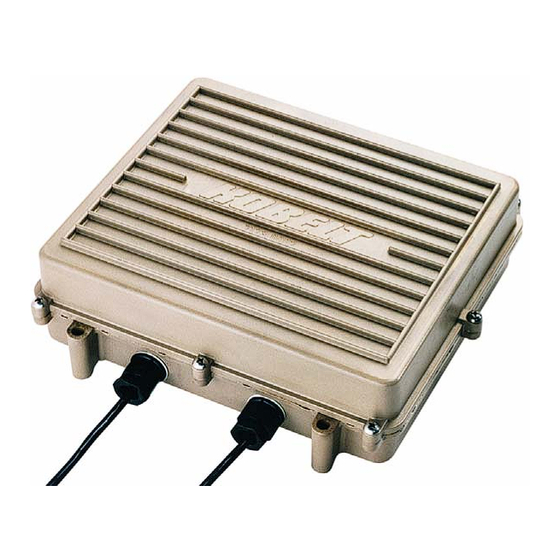
- Page 4 The Model 7173-K is a multi-optional driver Electronic Full Follow-up board (12- or 24-Volt DC) which can Amplifier Model 7173 control: Single steering system This unit is designed to accept the command See drawings 7173-001 / 7173-005 signal from our Models 7165, 7166, 7167,...
-
Page 5: Model 7173-K Components
MODEL 7173-K All dimensions in inches (mm) TYPICAL MULTIPLE STATION ARRANGEMENT... -
Page 6: Mounting The 7173-K Amplifier Unit
3. Follow-up (Rudder Feedback) Unit 4. Solenoid Interface Valve The Model 7173-K System is used to set the position (or the angle) to which the Rudder goes. The Amplifier Unit compares the respective command and feedback signals from the Controller and Follow-Up Unit. -
Page 7: Mounting The Model 7174 Rudder Feedback Unit
MOUNTING THE MODEL 7174 RUDDER FEEDBACK UNIT The Model 7174 or 7168 Follow-Up (Rudder Feedback Unit) must be mounted near the steering gear as shown in the diagram below. The output signals will then be calibrated with the tiller in place. -
Page 8: Wiring The System
The input power to the Model 7173-K Amplifier Unit is 11 VDC to 28 VDC. The power cable (2-conductor, #14-gauge) should be run from the switchboard through a customer-supplied on/off switch via a circuit breaker or fuse (8 amp). -
Page 9: Testing The System
Also, rudder limit adjustment can be achieved by adjusting rudder limit trim pots on 7173-K board or by adjusting the stroke on the feedback unit. NOTE: You must not allow the cylinder to continually push against the mechanical stops (hardover position). -
Page 10: Troubleshooting
- meter output voltage, replace if necessary Rudder hunts back - R17 or R31 deadband control in - reduce gain by turning and forth Model 7173-K Amplifier incorrectly counter-clockwise adjusted Rudder goes to a - defective potentiometer - replace hardover position... -
Page 11: Periodic Inspection
Some Kobelt components are equipped with inspection covers which can be removed for examination of internal parts. The following serves as a general inspection guideline for Kobelt engine control and steering control system components. All deficiencies have to be fixed and defective parts be replaced by a certified technician to ensure a reliable and safe operation.
Need help?
Do you have a question about the 7173-K and is the answer not in the manual?
Questions and answers