Table of Contents
Advertisement
Available languages
Available languages
Quick Links
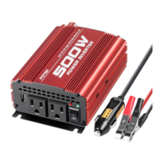
POWER INVERTER 500W
Inversor de Energía / Convertisseur électrique
OWNER'S MANUAL
MANUAL DEL USUARIO/GUIDE D' UTILISATION
WARNING
Pursuant to California Proposition 65,
this product contains chemicals known to the state of California to
cause cancer and birth defects or other reproductive harm. Wash hands after handling.
MODELS / MODELL / MODÈLES:
PI500-AP/ PI500-AP-RED
POWER INVERTER
Converts 12V DC Battery Power to AC Household Power
INVERSOR DE ENERGÍA
Convierte la energía de baterías de 12V de CD a 120V de CA de
energía doméstica
ONDULEUR DE PUISSANCE
Convertir la Puissance de batterie 12VCC à la Puissance du ménage
• 1 •
Advertisement
Table of Contents

Related Manuals for Potek PI500-AP


Summary of Contents for Potek PI500-AP
- Page 1 POWER INVERTER 500W MODELS / MODELL / MODÈLES: Inversor de Energía / Convertisseur électrique PI500-AP/ PI500-AP-RED POWER INVERTER Converts 12V DC Battery Power to AC Household Power OWNER’S MANUAL INVERSOR DE ENERGÍA Convierte la energía de baterías de 12V de CD a 120V de CA de energía doméstica...
-
Page 2: Important Safety Instructions
FEATURES IMPORTANT SAFETY INSTRUCTIONS SAVE THESE INSTRUCTIONS. • High-speed cooling fan • ON/OFF rocker switch To keep the inverter cool, the fan turn on • LED indicator 1. SAVE THESE INSTRUCTIONS. maintenance or cleaning. Turning off depend on the load on the inverter or Green indicates Power ON This manual contains important safety controls will not reduce this risk. - Page 3 4. OPERATING INSTRUCTIONS 1. Connect the inverter (see Connecting “beep”. This is normal.) Inverter Cables section. 5. Make sure the device to be operated 2. Switch the inverter’s ON/OFF switch is turned OFF. to the ON (I) position. 6. Plug the device into the inverter’s 3.
-
Page 4: Power Source
NOTE: If more than one device is to be damage the inverter and/or device. If 6. LED INDICATOR AND SHUTDOWN PROTECTION powered, start one device at a time, to you are using the inverter to operate avoid a power surge and overloading a rechargeable device, monitor the 3. -
Page 5: If The Inverter's Fuse Blows
7. IF THE INVERTER’S FUSE BLOWS 9. TROUBLESHOOTING polarity or a short circuit within the device PROBLEM POSSIBLE CAUSE REASON/SOLUTION which should not have to be replaced or equipment being operated. Red LED is on,audible Poor contact at terminals Unplug and reinsert the 12V plug under normal operating conditions. -
Page 6: Specifications
302-261-8788 (US) support@potekelec.com Input low voltage shutdown................10.0±0.5 VDC Output power overload shutdown level ...............550±50 W Input fuse .........................2x30 A @Potek.fans @PotekSupport AC receptacles.................Two, NEMA 5-15 USA USB port ......................One, 5V 2A @Potekelectronic Battery cables ....................10AWG, 21.6 in Cable with 12V accessory plug ..............16AWG, 35.4 in •... -
Page 7: Instrucciones Importantes De Seguridad
11. No utilice el inversor con un producto que puede causar el daño al inversor INSTRUCCIONES IMPORTANTES DE SEGURIDAD saca una potencia más alta que un y el producto. GUARDAR ESTAS INSTRUCCIONES. inversor puede proporcionar, es que eso 1. GUARDAR ESTAS INSTRUCCIONES Para reducir el riesgo de descarga eléctrica, Este manual contiene las instrucciones desenchufe la unidad desde el tomacorriente... - Page 8 3. CONEXIÓN DE CABLES DEL INVERSOR El inversor y la fuente de alimentación quite la tuerca, y la arandela plana del bloqueo de división. debenencontrarse en el modo Apagado. 3. Coloque el aro del conector IMPORTANTE: Asegúrese de conectar POSITIVO (ROJO) en el terminal su inversor solamente a una fuente de POSITIVO (ROJO) del inversor.
-
Page 9: Instrucciones De Operación
4. INSTRUCCIONES DE OPERACIÓN Conecte el inversor (véase la sección Encendido (I). Encienda el dispositivo. Conexión de Cables del Inversor). Para desconectar, reverse dichos Conmute el interruptor de Encendido / Apagado del inversor a la posición procedimientos. Encendido (/I). NOTA:Si más de un dispositivo serán El indicador LED VERDE se encend- encendidos, arranque un dispositivo cada erá, indicando que el inversor está... -
Page 10: Fuente De Alimentación
5. FUENTE DE ALIMENTACIÓN 6. INDICADOR DE LED Y PROTECCIÓN DE APAGADO operado excede la carga continua Su batería de automóvil media en carga La LED verde se enciende automática- El inversor de energía tiene un apagado completa proporcionará una fuente de mente cuando el inversor está... -
Page 11: Solución De Problemas
7. SI EL FUSIBLE DEL INVERSOR FUNDE 9. SOLUCIÓN DE PROBLEMAS Su inversor de energía está equipado con invertida o un cortocircuito dentro del PROBLEMA CAUSA POSIBLE SOLUCIÓN los fusibles, que no requerirán el reempla- dispositivo o el equipo que está en La LED roja está... -
Page 12: Especificaciones
Apagado de bajo voltaje de entrada ............. 10.0±0.5 VDC Nivel de apagado de sobrecarga de energía de salida ........550±50 W Fusible de entrada ......................2x30 A @Potek.fans @PotekSupport Receptáculo CA ................Dos, NEMA5-15 USA Puerto USB ...................... Uno, 5V 2A Cable de batería con abrazaderas.............. -
Page 13: Instructions De Securite Importantes
Branchez uniquement l’onduleur de N'utilisez pas l’onduleur avec un produit INSTRUCTIONS DE SECURITE IMPORTANTES puissance à une batterie 12V ou à une qui tire une puissance en watts supérieure CONSERVER CES INSTRUCTIONS alimentation électrique. N'essayez pas de à celle que l’onduleur peut fournir, car cela connecter l’onduleur de puissance à... - Page 14 3. CONNEXION DES CÂBLES DE L’ONDULEUR L’onduleur et l'alimentation électrique NÉGATIF (NOIR) bornes, retirez l’écrou, verrouillage de doivent être configurés en mode fractionnement et la rondelle plate. ARRET. 3. Placez le POSITIVE (ROUGE) IMPORTANT: Assurez-vous de connecteur d’anneau sur le positif connecter votre onduleur uniquement à...
- Page 15 4. MODE D’EMPLOI Pour déconnecter, inverser la procédure Connectez l’onduleur (voir section ci-dessus. procedure. Connexion des Câbles de l’onduleur. Mettre l'interrupteur marche / arrêt de NOTE:Si plusieurs appareils doivent être l’onduleur sur la position MARCHE (I). alimentés, démarrez un appareil à la fois L'indicateur LED VERT s'allumera, pour éviter une surtension et surcharge de indiquant que l’onduleur reçoit...
-
Page 16: Alimentation Electrique
5. ALIMENTATION ELECTRIQUE 6. INDICATEUR LED ET PROTECTION D'ARRÊT Votre batterie d'automobile moyenne à profondément déchargées. Le LED vert s'allume automatiquement fonctionnement dépasse la charge pleine charge fournira une alimentation L’onduleur de puissance aura un arrêt continue nominale de l’onduleur. lorsque l’onduleur est branché... -
Page 17: Dépannage
7. SI LE FUSIBLE DE L'INVERSEUR ARRETE A SAUTE 9. DÉPANNAGE Votre onduleur de puissance est équipé de dispositif ou la mise en marche d’équipe- PROBLÈME CAUSE POSSIBLE RAISON / SOLUTION fusibles qui ne doivent pas être remplacés ment. Le voyant DEL rouge est Mauvais contact aux Débrancher et réinsérer dans des conditions normales de... -
Page 18: Spécifications
Courant à vide typique (à la tension d'entrée nominale) ........0.5 ADC Arrêt de surtension de l'entrée ...............15.5±0.5 VDC Alarme de sous-tension d'entrée ..............10.5±0.5 VDC support@potekelec.com @Potek.fans Arrêt basse tension d'entrée ................. 10.0±0.5 VDC Niveau d'arrêt de surcharge de puissance de sortie ........... 550±50 W @potekelectronic @PotekSupport Fusible d'entrée .......................
Need help?
Do you have a question about the PI500-AP and is the answer not in the manual?
Questions and answers