
Related Manuals for Valeo SC600 Australien

Summary of Contents for Valeo SC600 Australien
- Page 1 BUS BODY ELECTRONICS SC600 AUSTRALIEN Operating instructions - Busdriver Rev. 21.11.2018 Id.No. DOK30605...
-
Page 2: Table Of Contents
BUS BODY ELECTRONICS Contents Contents List of Figures List of Tables Introduction Intended purpose Symbols used Description of the control panel Description of the display Modi overview Activation/deactivation 2.1.1 Activation 2.1.2 Deactivation Auto mode 2.2.1 Activation 2.2.2 Deactivation Configuring the blowers manually 2.3.1 Activating the controller manually 2.3.2... -
Page 3: List Of Figures
BUS BODY ELECTRONICS List of Figures Figure 1 - SC600 control panel .................. 4 Figure 2 - SC600 display ..................4 Figure 3 - SC600 mode overview ................5 Figure 4 - SC600 start display ................... 6 Figure 5 - SC600 deactivation ................... 6 Figure 6 - SC600 Auto mode activated ................ -
Page 4: Introduction
BUS BODY ELECTRONICS 1 Introduction 1.1 Intended purpose The SC600 is a system intended to control the HVAC components (heating, ventilation, air - conditioning) in buses, for example roof-top air-condition systems, heating devices, etc. It con- sists of a control panel (control device as an interface between human and machine) that is integrated into the dashboard. -
Page 5: Description Of The Control Panel
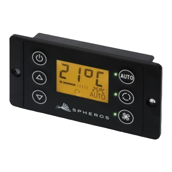
BUS BODY ELECTRONICS 1.3 Description of the control panel The control panel components are depicted and described in the following image. Figure 1 - SC600 control panel 1. Display 5. Function status light 2. On/off button 6. Blower button 3. UP button 7. -
Page 6: Modi Overview
BUS BODY ELECTRONICS 1.5 Modi overview The SC600 system includes 2 different modes – Operating mode and Error mode. SC600 Error detection Operating mode: Includes all of the mode: Mode to display all functions and infor- errors that occurred mation summa- rized under point 2 and their probability... -
Page 7: Use
BUS BODY ELECTRONICS 2 Use 2.1 Activation/deactivation 2.1.1 Activation Press button ➔ Sets the last configured temperature; Auto mode off Figure 4 - SC600 start display (Figure 4). 2.1.2 Deactivation Press button ➔ Display deactivated. Press button for 2 seconds until OFF appears ➔... -
Page 8: Deactivation
BUS BODY ELECTRONICS 2.2.2 Deactivation Press button if Auto mode is on ➔ Mode is off - corresponding status light and function symbol are off (Figure 9). Note Figure 9 - SC600 Auto mode deactivated When Auto mode is deactivated, the air conditioning com- pressor (after a run time of 90 seconds max.) and the heater are turned off. -
Page 9: Deactivating The Controller Manually
BUS BODY ELECTRONICS 2.3.3 Deactivating the controller manually Press button for 3 seconds ➔ Manual controller deactivated. Press button ➔ Manual controller deactivated. Figure 11 - SC600 recirculating air function 2.4 Fresh air/recirculating air function activated Press button when fresh air valves are open ➔... -
Page 10: Errors
BUS BODY ELECTRONICS 2.6 Errors Note If a system error occurs, the error symbol will appear on the display (Figure 13). 2.6.1 Error detection mode Figure 13 - SC600 errors 2.6.1.1 Activation Press buttons at the same time for 2 seconds ➔... -
Page 11: Error Overview
BUS BODY ELECTRONICS 2.6.2 Error overview Error code Component Cause Remedy F001-016 Not used ➢ Defective sensor F017 Pressure sensor ➢ Wiring harness de- fective ➢ Defective sensor F018 Duct/convector temper- ➢ Wiring harness de- ature sensor fective ➢ Defective sensor F019 Ice sensor ➢... - Page 12 Valeo Thermal Commercial Vehicles Germany GmbH Postfach 1371 – 82198 Gilching - Germany - Tel. +49 (0)8105 7721-0 - Fax 49 (0)8105 7721-889 www.valeo-thermalbus.com - service-valeobus@valeo.com...
Need help?
Do you have a question about the SC600 Australien and is the answer not in the manual?
Questions and answers