Table of Contents
Advertisement
Quick Links
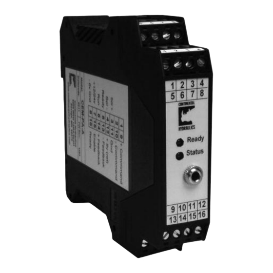
Description:
This closed loop position module provides synchronized motion. It may be applied in pairs, each
module driving a hydraulic cylinder for a "Master-Master" system of synchronized motion. This
pair of cylinders can quickly and accurately move hydraulic cylinder loads in unison. Or, it may
be applied in a "Master-Slave" mode, where up to three "Slave" axis will closely follow the
"Master" axis.
Position and velocity commands are from analog sources. Cylinder feedback is from an analog
source.
Stroke dependent deceleration is used to provide quick and repeatable positioning. Internal ramp
and velocity adjustments allow for easy system tuning.
A wide range of analog signals are accepted. User may select either voltage or current input
mode. These inputs are easily scaled to match system requirements.
Output is an analog voltage, 0 to +/- 10v, suitable for directly driving a proportional directional
valve with on board electronics.
This module is easily adapted to a variety of system requirements. All variables are user adjusted
with easy to use software on your Microsoft Windows laptop. Control variables are stored in non-
volatile memory internal to the module. All variables can be read by the laptop, and reproduced
exactly on other modules.
Technical Data:
Power Supply
Consumption
External Fuse
Voltage
Analog Inputs
Impendance
Current
Impendance
Resolution
Sample Time
(Speed Input) Voltage
(Speed Input) Impendance
Digital Outputs
Electrical Connection
Programming Port
Power and Signal
Ground
Page 1 of 15
Continental Hydraulics Installation Manual
CEM-MS-A
vDC 12 to 30 (including ripple)
mA
<100mA
A
3 (medium action)
vDC
0 to + 10
ohm
33k
mA
0 to + 20 (typ 4 to 20)
ohm
250
%
0.01
mS
1.0
0 to +10
vDC
ohm
90k
V
Logical 0 = < 2
(50mA max)
V
Logical 1 = ~ Power Supply
RS-232 3.5mm Stero Jack
4 strips with 4 screw terminals each
via DIN Rail
CEM-MS-A
Digital Inputs
V
V
Impendance
ohm
vDC
Analog Output
Voltage
Current
mA
Resolution
%
Housing
Module
Material
Combustability Class
UL94
Protection Class
IP
Working Temperature
C
Storage Temperature
C
Humidity
%
Electro Magnetic Compatibility
Emission
Immunity
Vibration Resistance
Logical 0 = < 2
Logical 1 = > 10
25k
0 to +/- 10
5 (max)
0.024
Snaps to 35mm DIN Rail EN 50022
Polyamide PA 6.6
V0
20
-20 to +60
-20 to +70
95 (non condensing)
EN 61000-6-2
EN 61000-6-3
EIC 60068-2-6
CHI 1013478 Jan 2013
Advertisement
Table of Contents

Subscribe to Our Youtube Channel
Related Manuals for Continental Hydraulics CEM-MS-A


Summary of Contents for Continental Hydraulics CEM-MS-A
- Page 1 Continental Hydraulics Installation Manual CEM-MS-A Description: This closed loop position module provides synchronized motion. It may be applied in pairs, each module driving a hydraulic cylinder for a “Master-Master” system of synchronized motion. This pair of cylinders can quickly and accurately move hydraulic cylinder loads in unison. Or, it may be applied in a “Master-Slave”...
-
Page 2: Functional Diagram
Continental Hydraulics Installation Manual Functional Diagram: CEM-MS Input +12 to 24v Scaling Command Speed 0 to +10v Profile Control Output Command Position Differential Input on Control Control Valve 0 to + 10v 4 to 20 mA Feedback Position Synch Ground... -
Page 3: Module Mounting Location
Continental Hydraulics Installation Manual Steps to install and configure a new application: Mount the module in a suitable location Connect the power supply Connect inputs and outputs Adjust analog inputs to voltage or current, and adjust input scaling Adjust analog output to match valve characteristics... - Page 4 Continental Hydraulics Installation Manual Stroke Dependent Deceleration: The CEM-MS module uses the position control theory of stroke dependant deceleration. When a new position is commanded, the initial motion profile is ramped and speed controlled in open loop mode. As the load travels, it soon gets to a preprogrammed point, termed the braking point. At the braking point, the module converts to closed loop control, constantly adjusting the speed of the load, homing in on the final stopping point.
- Page 5 Continental Hydraulics Installation Manual Stroke Dependent Deceleration (continued): System velocity command can be either external or internal. VS can be set to either INT or EXT. INT is default. INT requires the speed to be set with the VELO parameter.
- Page 6 Continental Hydraulics Installation Manual Synchronization Control: A two axis system may be configured as either “Master – Master” or “Master – Slave”. “Master – Master” averages the synchronization error between the two cylinders. Command Valve Cylinder 15/16 CEM-MS Enable Position "Master"...
- Page 7 Continental Hydraulics Installation Manual Synchronization Control (cont): Synchronization control function diagram: Input CEM-MS Synch Scaling Position Command Ramp Axis Control A:A A:B D:A D:B Axis Feedback Synch Control GL:P GL:T1 Synch Feedback GL:P and GL:T1 parameters: GL:P sets the synchronization gain. As with the basic single axis control, reducing the braking distance will increase the system gain, but has the potential to promote instability.
- Page 8 Continental Hydraulics Installation Manual Adjust module output to match valve requirements: The CEM-MS module has a 0 to +/-10v differential output. This output is designed to directly interface to proportional valves with on board electronics. This output signal may be configured to more closely match the valve characteristics. The...
- Page 9 Continental Hydraulics Installation Manual Adjust module output to match valve requirements (continued): When using a proportional valve with an underlap spool (“zero” lap), the flow gain in the area of the underlap is about double that outside the underlap area. Adjusting TRIGGER and MIN:A and MIN:B as suggested will give more stable results.
- Page 10 Continental Hydraulics Installation Manual Command input with Voltage: An analog source voltage may be either “differential” or “ground referenced”. The CEM-MS accepts an analog position command and feedback inputs that are ground referenced. The optional velocity command input is a differential input. Examples are shown for position command only, feedback signals are wired to pin 14(+) and pin 11 (GND) and to pin 6 (+) and pin 11 (GND).
- Page 11 Continental Hydraulics Installation Manual Command input with Current: The analog position and feedback inputs may be software set to accept a current command. Either input can be individually adjusted to accept either voltage or current. When current is chosen, a 250 ohm resistor is internally inserted across terminals 13 and 11, and/or between terminals 14 and 11.
- Page 12 Continental Hydraulics Installation Manual Scaling of analog input: This module has a native analog voltage input range of 0 to +10v for command and feedback. These inputs may be scaled and offset with software to allow a wide variety of input voltages. A few examples are: 0 to +10v, 0 to +5v, +1 to +5v, +0.5 to +4.5v...
- Page 13 Continental Hydraulics Installation Manual Swapping polarity with the POL parameter: The output drive polarity may be swapped with the POL command. Valid parameter values are “+” and “-“. (Default = +). Adjustment of SENS internal monitoring function: This module has optional input and internal monitoring functions. The module can monitor command inputs for proper range.
- Page 14 Continental Hydraulics Installation Manual START (RUN) (pin 7) digital input: START (RUN) is a digital input that is active high. Bringing pin 7 high (while holding pin 8(ENABLE) high), forces the module into closed loop position control mode. If RUN is removed during an active motion profile, the output to the valve is ramped to zero during the preset emergency stop distance parameter (D:S).
-
Page 15: Led Function
Continental Hydraulics Installation Manual LED function: Green (Ready) Steady on System OK Blinking 4 to 20mA current input command is out of range Blinking internal error sensed Yellow (Status) Steady on Synch error is within InPOS tolerance Synch error is outside InPOS tolerance Parameter monitoring using software: The following parameters may be monitored in real time using Windows configuration software.
Need help?
Do you have a question about the CEM-MS-A and is the answer not in the manual?
Questions and answers