Advertisement
Quick Links
CAUTION – Before performing any service
operation on any Directional Control Valve,
be sure that all pressure has been relieved
from BOTH SIDES of the system.
CAUTION – Before performing any service
operation on any Directional Control Valve,
disconnect or lock off power supply.
CAUTION – Before manually actuating any
Directional Control Valve, be sure that any
resulting machine function will not endanger
persons or equipment.
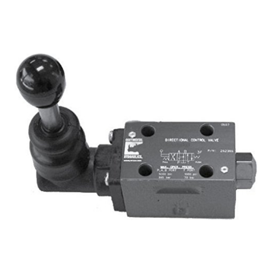
PRODUCT IDENTIFICATION
Each Directional Control Valve has an Ordering Code
stamped on its top label. See Figure 1 for the location
of the Ordering Code.
Ordering
Code
1101
VMD03M - _ _ - G - _ 10 - A
Basic Valve
Function
Spool Type
Seal Type
Mechanical Options
Operator
Design Letter
This Service Booklet applies to products with Ordering
Codes like the sample in Figure 2.
SAVAGE, MN. U.S.A. 55378
VMD03M-1A-G-10-A
P,A,B
5000 PSI (345 BAR)
T
3000 PSI (207 BAR)
b
A
B
a
3A
P
T
SERVICE MANUAL
GENERAL SPECIFICATIONS
RECOMMENDED FLUID
Petroleum, water-based fluids (not more than 40%
water) and most phosphate esters. Other fluids may be
acceptable, but special O-rings may be required. Viton
seals standard.
FLUID TEMPERATURE RANGE
Fluid temperature up to 200° F. (93° C.) will not
appreciably affect valve performance. However, for
safety reasons, temperatures above 130° F. (54° C.)
are not recommended.
RECOMMENDED OPERATING VISCOSITY
80 to 350 SUS (16 to 70 cSt).
FILTRATION
ISO 18/16/13 or better.
MOUNTING POSITION
Any unrestricted position acceptable. Horizontal
mounting preferred.
NFPA FLOW PATH/ACTUATING PATTERN
MANUAL:
Push lever – connects flow to cylinder port A.
Pull lever – connects flow to cylinder port B.
The NFPA flow path/actuating pattern is reversed for
Code L Spools
GENERAL INFORMATION
MANUAL ACTUATED – Spring centered and spring
offset valve types will be spring positioned unless
actuated continuously. Detented, no-spring valves
may be actuated momentarily. When solenoid is not
actuated, the spool will remain in last position attained,
provided there is no severe shock, vibration or
pressure surge.
Pressure surges in a common tank line serving these
and other valves can be great enough to cause
Figure 1
inadvertent valve shifting. This is particularly critical in
the no-spring, detented type valves. Separate tank
lines may be necessary.
NOTE: Any sliding spool valve held shifted under
pressure for long periods may stick and not spring
return due to fluid residue formation. To prevent
sticking, valves should be cycled periodically.
PREVENTIVE MAINTENANCE
After Directional Control Valves have been put in
operation, provide periodic inspection and
maintenance. The check points listed below will assist
you in extending the life of your Continental valves.
Figure 2
Fluid Operating Temperature – Fluid temperature at
the reservoir during operation should be kept between
100° F. and 130° F. (38° C. and 54° C.).
Fluid Cleanliness – Control particle contamination by
changing or cleaning all filter elements periodically
BEFORE they become clogged and start to by-pass.
Form No. R133.00 11/03
VMD03M Manual Actuated
Directional Control Valves
"A" Design Series
1
Advertisement

Related Manuals for Continental Hydraulics A Design Series


Summary of Contents for Continental Hydraulics A Design Series
- Page 1 SERVICE MANUAL VMD03M Manual Actuated Directional Control Valves “A” Design Series GENERAL SPECIFICATIONS RECOMMENDED FLUID Petroleum, water-based fluids (not more than 40% water) and most phosphate esters. Other fluids may be acceptable, but special O-rings may be required. Viton seals standard. FLUID TEMPERATURE RANGE Fluid temperature up to 200°...
- Page 2 Authorized Repair Center for repair. disassembled. Contact your local Distributor or Continental Hydraulics Continental valves are precisely machined to exacting for details. tolerances. Do not force any parts, or overtighten If interchanging spool types or making other threaded fasteners.
- Page 3 VMD03M Directional Control Valve Assembly ITEM CODE PART # DESCRIPTION QUANTITY REQUIRED 1 & 3 350231 Manual Operator Assembly 350232 Manual Operator Assembly 350233 Manual Operator Assmbly 253973 End Plug Asembly. 252260 Drive Pin 450913 A Spool 450915 B Spool 450916 F Spool 450987...
- Page 4 12520 Quentin Avenue South Savage, MN 55378 Phone: (952) 895-6400 Fax: (952) 895-6444 www.continentalhydraulics.com Because Continental Hydraulics is continually improving its products, specifications and appearance are subject to change without notice. Form No. R133.00 11/03 © 2003 Continental Hydraulics Printed in U.S.A.
Need help?
Do you have a question about the A Design Series and is the answer not in the manual?
Questions and answers