Table of Contents
Advertisement
Quick Links
NOTE:
Please read all instructions
carefully before using this
product
Table of Contents
Important Precautions
Components
Assembly
Operation and Adjustment
Maintenance
Parts List
Warranty
Model
JX-663SW
Retain This
Manual for
Reference
161101
OWNER'S
MANUAL
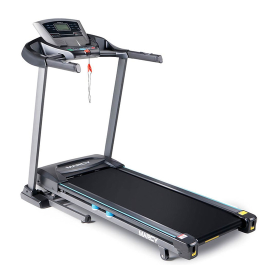
MARCY JX-663SW
Motorized Treadmill
With Auto Incline
IMPEX
2801 S. Towne Ave, Pomona, CA 91766
Tel: (800) 999-8899
www.marcypro.com
support@impex.fitness.com
INC.
®
Advertisement
Table of Contents

Related Manuals for Impex MARCY JX-663SW

Summary of Contents for Impex MARCY JX-663SW
- Page 1 NOTE: Please read all instructions carefully before using this product Table of Contents Important Precautions MARCY JX-663SW Components Motorized Treadmill Assembly With Auto Incline Operation and Adjustment Maintenance Parts List Warranty Model JX-663SW Retain This Manual for Reference 161101 OWNER'S...
-
Page 2: Table Of Contents
BEFORE YOU BEGIN Thank you for selecting the MARCY MOTORIZED TREADMILL WITH ® AUTO INCLINE JX-663SW by IMPEX INC. For your safety and benefit, read this manual carefully before using the equipment. As a manufacturer, we are committed to provide you complete customer satisfaction. If you... -
Page 3: Important Precautions
To reduce the risk of serious injury, read all important precautions and instructions in this manual and all warnings on your treadmill before using your treadmill. Impex assumes no responsibility for personal injury or property damage sustained by or through the use of this product. -
Page 4: Components-Parts
19. The treadmill is capable of high speeds. 24. Do not change the incline of the treadmill Adjust the speed in small increments to by placing objects under the treadmill. avoid sudden jumps in speed. 25. Never insert any object into any opening 20. - Page 5 Components Main Frame Left Mast Cover Right Mast Cover Safety Key Hardware pack Mp3 Link Lubricating Oil Power cord Console Right Console Mast Left Console Mast...
-
Page 6: Components-Fixings
Components Ø ⅝” Washer × 14 M8 x 3 ⅛” Allen Bolt × 2 M8 x ¾” Allen Bolt × 4 Ø ⅜” Lock Washer × 14 ST4.8 x ⅝” Phillips Screw × 2 M8 x 3 ⅛” Allen Bolt × 4 M8 x ⅝”... -
Page 7: Assembly
Assembly Main wire 84 87 54 66 87 84 Step 1 a. Slide and Pull the Main wire from the bottom of the Console Mast (4) to the upper opening. b. Fix each Console Mast (3&4) to the Base Frame (1) using four M8 x 3 ½” Allen Bolts (54), two M8 x 3 ⅛” Allen Bolts (66), four M8 x ⅝”... - Page 8 Console B’ A’ Step 2 a. Connect the wires as shown in the diagram; b. Attach each side of the Console to the two Console Mast (3&4) by using four M8 x ¾” Allen Bolts (68), four Ø ⅝” Lock Washers (87) and four Ø ⅝” Washers (84). c.
- Page 9 Groove Fastener Step 3 Attach the Mast Cover (20&21) to the Console Mast (3&4), press the Fastener (on the end of the Mast Cover ) into the Groove (on the Base frame 1 ),and then using two ST4.8 × ⅝” Dome Head Philips Screw (71).
- Page 10 Fold and Unfold Grip and hold the Rear Roller and lift up running deck. Fold up the running deck until the Hydraulic Bar is clicked firmly locked. After folding the Treadmill; grip and hold the Rear Roller bar, and then push or pull to transport.
-
Page 11: Operation And Adjustment
Please unplug the power source and push down the button, and then plug in the power cord and turn on the switch to restart your workout. If the button pops up again, please contact Impex. IMPORTANT NOTICE SAFETY KEY: The treadmill will only work if the safety key (45) is properly locked in the provided notch of the console. - Page 12 CONSOLE DIAGRAM A Quick Incline Select B Quick Speed Select C Start D Stop E Incline- F Speed+ G Incline+ H Speed- I MODE J Prog K Heart rate L Time M Cal N Dis. O Speed Q Incline+ R Incline- S Speed+ T Speed-...
- Page 13 FUNCTIONS AND OPERATIONS TECHNICAL SPECIFICATION SAFETY KEY Time---------------------------------0:00--99:59 Min The safety key must be placed into the Speed-------------------------------0.5--10.0 mile/h magnetic recess on the console in order to Distance----------------------------0.0--99.9 mile operate the treadmill. Always place the Calorie------------------------------0.0--999Kcal safety key on its position and attach the clip Incline-------------------------------0--15% to your clothing at your waist before Pulse--------------------------------50--200 Times/ Min...
- Page 14 STARTING YOUR TREADMILL WORKOUT MODEL Turn on the treadmill, and press “Start” button Turn on the treadmill, press the “Mode” key two times, and the “Dis” (Distance) window on the console. Press “Speed +” or “Speed -” button to adjust flashes and displays “1.00”, which is the speed or press handle “Speed + or Speed -”...
- Page 15 Program Workout Model (P01—P10) In this mode, the user has a choice of Program P01 down three and start operation. The start speed – Program P10. depends on the program you have chosen. Press the “Prog. ” button, the “Speed” window will display “P01”...
- Page 16 BODY FAT ANALYSIS Turn on the treadmill, press “PROG” button until user’s body height 67 inch. Press “Speed +” or the “Speed ” window displays “FAT”. “Speed -” button or press “Incline +” or “Incline -” Press the “MODE” button again, the “Time” key to select your correct body height.
-
Page 17: Maitenance
Maintenance Proper maintenance is very important to ensure a STEP 2: Repeat STEP 1 for the right belt tension faultless and operational condition of the treadmill. bolt. You must be sure to turn both bolts the same Improper maintenance can cause damage to the number of turns, so the rear roller will stay square treadmill or shorten the life of the product and relative to the frame. - Page 18 CENTERING THE RUNNING BELT 1. Start the treadmill without anyone on the running belt, press “Speed+” button until speed reaches 4mile/h. 2. Observe whether the running belt is toward the right or left side of the deck. a) If toward the left side of the deck, using 6# Allen Wrench, turn the left adjustment bolt clockwise 1/4 turn and let the running belt find its new position;...
- Page 19 DECK LUBRICATION The treadmill is pre-lubricated. However, it is CLEANING recommended to check the lubrication of the Regular cleaning of the belt ensures a long treadmill regularly, to ensure an optimal operation product life. of the treadmill. Warning: The treadmill must be turned off to avoid electric shocks.
- Page 20 TROUBLE SHOOTING Symptom Cause and Check Solution Safety Key not in the position Re-locate the safety key in the correct position No signal to Controller from A: Check the Main Controller Wire console B: Replace the PCB Board A: Check the wire from motor to controller B: IGBT breakdown, Replace the controller Motor communication error C: Check the power voltage if 50% lower than rate...
-
Page 21: Suggested Stretches
EXERCISE INSTRUCTIONS Each workout should include the following three parts: 1. The Warm Up Phase This stage helps get the blood flowing around the body and the muscles working properly. It will also reduce the risk of cramp and muscle injury. It is advisable to do a few stretching exercises as shown below. - Page 22 3. The Cool Down Phase This stage is to let your Cardio-vascular System and muscles wind down. This is a repeat of the warm up exercise e.g. reduce your tempo, continue for approximately 5 minutes. The stretching exercises should now be repeated, again remembering not to force or jerk your muscles into the stretch.
-
Page 23: Exploded Diagram
EXPLODED DIAGRAM... -
Page 24: Parts List
JX-663SW PARTS LIST PART NO DESCRIPTION SIZE QUANTITY Base Frame Running Stage Left Console Mast Right Console Mast Console Frame Incline Frame Front Roller Rear Roller Motor Support Incline Motor Wheel Running Deck Running Belt Side Rail Console Housing Back Cover Bottom Cover Screen Cover Motor Cover... - Page 25 Pulse Sensor Motor Safety Key Controller Inductor Filter Switch Over Current Protector Power Socket Power Cord Short Cord M8 x 3 ½” Allen Bolt PC Board Magnetic Conductive Plate MP3 Link Speaker Sticker Hydraulic Bar Ø 1” x Ø ⅝” Washer M8 x ⅞”...
- Page 26 Ø ⅛” Washer Ø ⅛” Lock Washer M8 x ⅝: Allen Bolt MP3 Module Function Board St4.8 x ½” Dome Head Philips Screw Safety Key Plug M10 x 1 ¾” Allen Bolt M10 x 2 ½” Allen Bolt M8 x 1 15/8” Allen Bolt ST4.8 x ¾”...
-
Page 27: Limited Warranty
IMPEX. IMPEX is not responsible or liable for indirect, special or consequential damages arising out of or in connection with the use or performance of the product or other damages with respect to any economic loss, loss of property, loss of revenues or profits, loss of enjoyments or use, costs of removal, installation or other consequential damages or whatsoever natures.
Need help?
Do you have a question about the MARCY JX-663SW and is the answer not in the manual?
Questions and answers